
RockWorks | Utilities | Solid | Filters | Smoothing Filter
This program reads an existing solid model and averages the G-values based on a user declared "filter" size. The smoother can be run 1 or more times, to get rid of spurious "noise" within the model and bring out regional trends.
! This program is used to smooth an existing model, after it has been created. The same options are offered during model generation.
Feature Level: RockWorks Basic and higher
Menu Options
Step-by-Step Summary
- 3D Log Design
If you decide to include logs with this diagram (3D Solid Diagram | Striplogs), click on this tab at the top of the window to set up how you want the 3D logs to look.
See Visible Item Summary and Using the 3D Log Designer for details.
- Rules & Filters
Use these tabs at the top of the window to apply spatial filters, time/date filters, or stratigraphic rules to data being displayed in your 3D striplogs. (More info)
- Input/Output Models:
- Input Model: Click to the right to browse for the name of the existing RockWorks solid model (.RwMod file) that the program is to read and filter.
- Output Model: Click to type in the name to assign to the new solid model that the program will create, which results from the smoothing operation.
- Options:
- Iterations: Enter the number of times the entire model should be run through the smoother. You can enter a value from 1 to 1,000.
- Type of Smoothing:
- Box: Choose this for a simple "moving box filter" in which the voxels are re-assigned new values based on a distance-weighted average of all the original nodes that reside within the box. This is the faster of the two options, but can possibly create more edge effects.
- Box Filter Dimensions (Voxels): These settings establish the horizontal and vertical filter size, which define how many adjacent nodes should be used when computing the average (smoothed) G-value for each model node.
- X-Offset (voxels): Click here to enter the "depth" of the horizontal filter. If you enter "1", then each node will be assigned the average of itself and the 8 nodes immediately surrounding it, 1 layer deep horizontally. If you enter "2", the node will be assigned the average of itself and the 24 nodes immediately surrounding it, 2 layers deep. When in doubt, enter "1".
-
- Y-Offset (voxels): Click here to enter the depth of the vertical filter. Entering "1" will set each node to the average of itself and the 9 nodes immediately above it and the 9 nodes immediately below. When in doubt, enter "1".
-
- Cylinder: Choose this for a cylindrical filter, with dimensions defined in project units. This is the slower of the two options but can create smoother output.
- Filter Dimensions (Project Output Units)
- Automatic: Choose this for the filter dimensions to be set automatically by the program. It will set the radius of the search cylinder to 150% of the model X-spacing and 150% of the model Z-spacing.
- Manual: Choose this to set the radius and height manually.
- Radius: Enter the radius of the smoothing cylinder in your project units.
- Height: Enter the height of the smoothing cylinder in your project units.
- Warped Smoothing: Check this item if the smoothing cylinder is to follow along the contours of a grid model. This is especially valuable if you have requested that the model be interpolated along the warping surface.
- Surface Grid: Click here to browse for the name of the RockWorks grid model (.RwGrd file) that represents the ground surface. This is important to counteract a deep and highly contoured smoothing grid as you get near the surface of the model.
- Warping Grid: Click here to browse for the name of the grid model to serve as the warping grid.
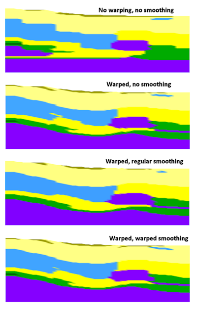
Here are some examples of a lithology model, shown in cross section, created with no warping, with warping, with regular smoothing, and with warped smoothing.
-
- Smoothing Method:
- Averaging: (Default) This method reassigns the node value based at the surrounding voxels (within the filter). This should not be used with lithology or stratigraphy solids.
- Classification: This method reassigns the node value based on the most frequently occuring value within the surrounding voxels. The classification filter is designed to be used when smoothing the contents of a lithology model or stratigraphy solid where you don't want the node values to be averaged but grouped.
- Tie-Breaking Methodology: Use this setting to define how RockWorks resolves instances in which a smoothing region contains an equal number of different voxels. For example, if the smoothing box encounters 1 clay voxel (G="0"), 18 gravel voxels (G="1"), and 18 sand voxels (G="2"), the tie-break option you choose will decide whether the smoothed voxel is assigned a value of "2" (Highest G) or "1" (Lowest G).
- Highest G: Choose this option if the classification filter should use the highest G value in the case of a tie.
- Lowest G: Choose this option if the classification filter should use the lowest G value in the case of a tie.
- Selective Smoothing:
- Do Not Smooth Selected G Values: Check this box if you want to enter a minimum and maximum G value range which are to be exempt from the smoothing process. This can be very helpful if you have "sacrosanct" voxels (e.g. faults and marker beds) that you do not wish to smooth.
- G-Min: Type in the minimum G value which will exempt a node from smoothing.
- G-Max: Type in the maximum G value which will exempt a node from smoothing.
-
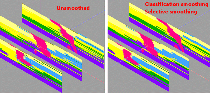
In the example below, an unsmoothed lithology model is shown in 3D panels (left side). On the right, the lithology model was smoothed very slightly, using the classification method, to get rid of some of the small material crenulations. In addition, a Selective filter was applied for the pink intrusive material so that it would not be smoothed at all.
- 3D Solid Diagram
Insert a check here to display the output solid model as a 3D diagram.
Click this tab to set up the diagram options.
- Block Diagram
- Isosurface: Click in the Isosurface radio button to display the solid model as if enclosed in a "skin." This view will be smoother than a voxel display. (More info)
- Isomesh: Check this box to plot a series of polylines that represent three-dimensional contours at a user-defined cutoff. Click this tab to establish the settings. (More info)
- Voxels: Click in the Voxels radio button to represent the solid model in the 3D display as color-coded voxels. You can choose to display either the Full Voxel, or just the Midpoint. Display of the midpoint only can significantly improve display time for huge models.
- Filter: Check this option if you want to restrict the isosurface or voxel display to a specific data range. This does not affect the model, only the display of the model. Enabling this permits you to create an initial display in RockPlot3D that eliminates the need to manually change the display attributes. More importantly, this capability if essential for initially displaying the solid in a pre-filtered state when creating animations and Playlist scripts.
! These filter settings can be changed once the diagram is displayed in RockPlot3D.
- Color Scheme: Choose the color scheme for the block model - automatic, table-based, etc. (More info)
- Striplogs: Check this item to include 3D logs with the solid model display. Click the 3D Log Design button at the top of the window to set up how you want the logs to look.
- XYZ Clipping: Check this sub-item if you want to restrict the logs to a particular spatial area. (More info)
- Other 3D Solid Diagram Options: Use these checkboxes to append other layers to your 3D scene. (Summary)
- Draped Image: Include an image in this 3D scene, draped over an existing grid surface. (More info)
- Floating Image: Include an image in this 3D scene, floating at a specified elevation. (More info)
- Perimeter Cage Include a 3D reference cage around the solid diagram. (More info)
- Legends: Include one or more legends with the diagram.(More info)
- Infrastructure: Display buildings, pipes, or other infrastructure with your 3D scene. (More info)
- Faults: Include 3D fault ribbons with this scene. (More info)
- Other 3D Files: Include other, existing, RockPlot3D ".Rw3D" files in this scene. (More info)
- Output Options: Use these settings to define whether the output scene is to be saved (or displayed as "untitled"), how the file should be named, and whether it is to be displayed after it is created. It also offers export options. (More info)
- Double-check that you have a real number RockWorks solid model which will be the input file for this program.
- Select the ModOps | Solid | Filters | Smoothing menu option.
- Enter the requested menu settings, described above.
- Click the Continue button to proceed.
RockWorks will load the input file, compute the new value for each solid model node using the requested filter size. This process will be repeated for each node in the entire source model. If Iterations was set to >1, the entire model will be passed though the "smoother" for the requested number of times. The resulting node values will be stored in a new solid model on disk under the output file name you selected. If you have requested a diagram, it will be displayed in a RockPlot3D tab.
- You can adjust any of the input options via the main Options tab to the left, and then click the Continue button again to regenerate the model and display.
- View / save / manipulate / print the image in the RockPlot3D window.
 Back to Solid Menu Summary

RockWare home page