RockWorks | Borehole Operations | Stratigraphy | 2D Isopach Map
Use this program to:
- Read a listing of stratigraphic contacts from the Borehole Manager database.
- Interpolate a grid model representing the top or base of the selected top formation, across the project area.
- Interpolate a grid model representing the top or base of the selected lower formation, across the project area.
- Subtract the lower surface from the upper, creating a thickness grid model.
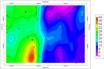
- Create a 2Dcontour map representing the isopach grid model, with a variety of map layers.
- Plot the map in RockPlot2D.
Feature Level: RockWorks Standard and higher
Menu Options
Step-by-Step Instructions
- Rules & Filters: Use the tabs at the top of the window to apply filters and rules for this program. (More info)
- Spatial Filter: Filter the input data for the surface models based on XYZ location. Note that these tools filter the data that is passed to the modeling procedures. This is distinct from the filters that are applied once the model is completed, and described below.
- Time Filter: Filter any T-Data or Aquifer data in map layers, if activated.
- Stratigraphic Rules: Apply stratigraphy rules for stratigraphic surfaces.
-
- Contact Options
Click here to specify the formation(s) whose thickness is to be modeled.
- Unit Top: Click on the formation name to the right to select the stratigraphic unit whose top or base is to represent the upper surface of the isopach model.
- Top of Unit: Click this radio button if the upper surface of the isopach model is to be the top of the selected formation.
- Base of Unit: Click this button if the upper surface of the isopach model is to be the base of the selected formation.
- Unit Base: Click on the formation name to the right to select the unit whose top or base is to represent the lower surface of the isopach model.
You can specify different formations for the top and the base, and the entire thickness between will be computed. The formation names that are listed here are read from the current Stratigraphy Types Table.
- Top of Unit: Click this radio button if the lower surface of the isopach model is to be the top of the selected formation.
- Base of Unit: Click this button if the lower surface of the isopach model is to be the base of the selected formation.
- Truncate Base: Check this box to constrain the lower surface from extending above the upper one, which can happen in areas with low control.
The isopach is generated by subtracting the lower surface elevations from the upper. If the surfaces cross, a negative thickness value will result, which (for obvious reasons) doesn't make much sense. This base truncation option tells the program to compare the surfaces before subtraction and truncate base grid elevations where they exceed the upper. The subtraction operation would then generate a thickness value of zero (pinched out) in those areas.
- Gridding Method
Click on this tab to establish the gridding method (aka algorithm), the grid dimensions, and other gridding options.
- Dimensions: Specify how the grid dimensions are to be established. Unless there's a specific reason to do otherwise, you should probably leave the grid dimensions set to the current output dimensions.
- Algorithms: Select a gridding method from the list, and establish any method-specific options which are displayed.
- Options: Click this tab to establish the other general gridding options (declustering, logarithmic, high fidelity, etc.).
- Save Grid Model
Insert a check here if you wish to save the thickness grid model that will be illustrated in the map. You might, for example, wish to use the RockWorks Utilities "Grid" menu tools to edit the model.
Click on this tab to assign the grid file name, such as "morrison-thickness.RwGrd".
- 2D Grid Map
Check this box to display the output grid as a 2D map at this time.
Click this tab to set up the 2D map layers (bitmap, symbols, labels, line contours, color-filled contours, labeled cells, map border, etc.).
- Output Options
- Save Output File: Check this to assign a name for the map in advance, rather than displaying it as Untitled.
- Automatic: Choose this option to have RockWorks assign the name automatically. It will use the name of the current program plus a numeric suffix, plus the ".Rw2D" file name extension.
- Manual: Choose this option to type in a name of your own for this file.
- Display Output: Check this option to have the resulting map displayed in RockPlot2D once it is created.
-
Follow these steps to create a 2-dimensional contour map that represents the thickness of a single stratigraphic unit or adjacent units.
- Access the RockWorks Borehole Manager program tab.
- Enter/import your data into the Borehole Manager database. This tool specifically reads location, orientation (if any), and stratigraphy data.
- Select the Stratigraphy | Stratigraphic Thickness | 2D Isopach Map menu option.
- Enter the requested menu settings, described above.
- Click the Continue button to proceed.
The program will read the depth intervals for the selected stratigraphic unit(s) as listed in the project's Stratigraphy table. It will internally translate depths to elevations based on the boreholes' surface and downhole surveys. It will create two background grid models, of the top-formation's upper or lower elevations and of the base-formation’s upper or lower elevations, using the selected gridding method. It will then subtract the elevations in the lower-grid from those in the upper-grid, thus creating a thickness model. If you have requested, the model will be stored under the specified name on disk. From this model it will create a 2-dimensional map with the selected layers. The map will be displayed in a RockPlot2D tab in the Options window if requested.
- You can adjust any of the program settings in the Main Options tab and click Continue button to regenerate the isopach model and the map.
- View / save / manipulate / print / export the map in the RockPlot2D window. (More into)
 Back to Stratigraphy Menu Summary

RockWare home page