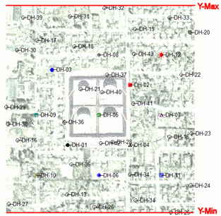
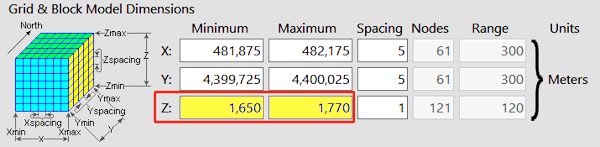
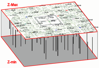
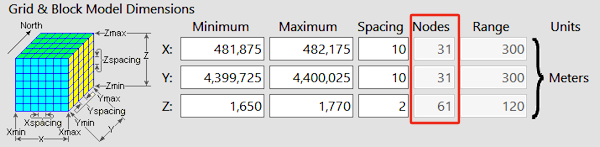
The Grid & Block Model Dimensions are established in the Dimensions tab in the RockWorks Project Settings. These will define the coordinate extents of your project area, from west-to-east along the X axis, from south to north along the Y axis, and from lowest to highest elevations along the Z axis.
If the Dimensions tab is not visible, click the small button to the left of the project folder name. This toggles between "+" (expanding) and "-" (hiding) the Project Settings tabs.
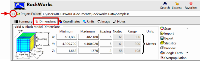
These settings are really important in RockWorks. They are used to...
- dimension grid models and solid models you create.
- scale all of your map and diagram components - text, log widths, etc.
The coordinates can be typed in by hand, scanned from your data, and imported from file. You can view statistics, preview the extents, show them in Google Earth, and identify model cells which are overpopulated. See the Dimensions tab for details.
The Grid & Model Dimensions are stored in the current project database. Though these dimensions can be overridden during model and diagram creation, we generally recommend that you utilize these dimensions for your grid models, solid models, and diagram annotations for ease and consistency. For example, all the project grid models must have the same dimensions and node densities if you wish to perform any mathematical or filtering operations with them. The same holds true for solid models.
For new projects the dimensions will default to a range of 0 to 100 along all axes.
- Type them in. If you know the minimum and maximum coordinates for your project, you can type them right in to the Grid & Block Model Dimensions prompts.
-OR-
- Scan Data. If you don't know the coordinates of your project extents off the top of your head (and most of us don't), you can have the program scan your data to determine the coordinate extents.
- Review: Review the scanned settings to be sure they make sense. THIS IS REALLY IMPORTANT.
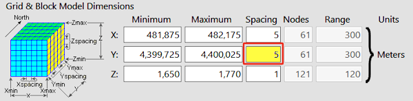
Minimum and Maximum Dimensions - Spacing Settings - Number of Nodes
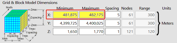
- Minimum and Maximum Dimensions:
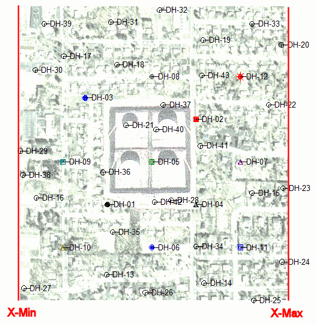
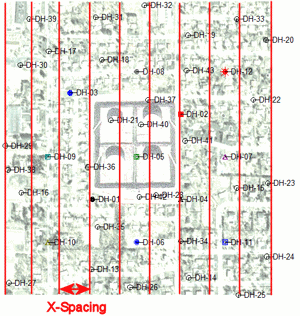
- X-Minimum and X-Maximum: These coordinates define the western and eastern map extents of your project.
-
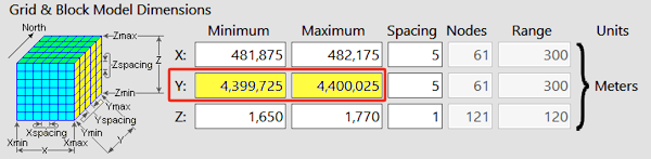
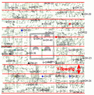
- Y-Minimum and Y-Maximum: These coordinates define the southern and northern map extents of your project.
-
- Z-Minimum and Z-Maximum: These coordinates define the elevation extents of your project.
-
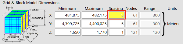
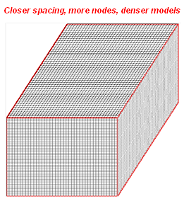
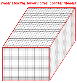
- Spacing Settings: These settings pertain to interpolated models only. They represent the spacing between nodes along each axis and (hence) the density of the models the program will create. LOOK AT THESE NUMBERS. Node density affects the quality of the model and the time necessary to generate it.
- The X-Spacing will define how far apart grid and solid model nodes will be from west to east. It is declared in your map units.
-
- The Y-Spacing will define how far apart grid and solid model nodes will be from south to north. It is declared in your map units.
-
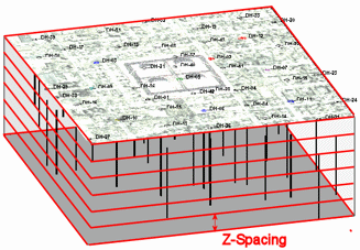
- The Z-Spacing will define how far apart grid and solid model nodes will be from the lowest elevation to the top elevation in the project. It is declared in elevation units. (Which should, incidentally, be the same units – feet or meters – as your X,Y map units.)
-
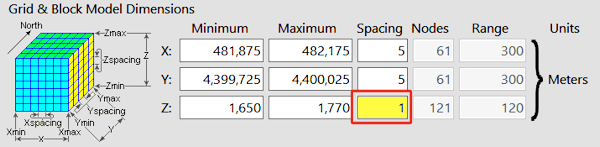
- Number of Nodes: These prompts display the number of nodes that will be generated along each axis. These are computed automatically, based on the dimensions divided by the spacing. You cannot edit the node settings; to adjust the density, edit the spacing.

- If the default number of X and Y nodes is too high or too low, you can either hand-edit the spacing value(s) or adjust the Horizontal Resolution (under the Borehole or Datasheet scan options) and re-scan.
- If the default number of Z (elevation) nodes is too high or low, you can hand-edit the spacing value or adjust the Vertical Resolution (under the Borehole or Datasheet scan options) and re-scan.
- Denser is not always better. You might create less-dense models on trial runs and increase the density only if you feel the detail of the data is not being represented.
- Keep in mind that a solid model with 50 x 50 x 50 nodes (125,000 total) requires one-eighth the computations of a 100 x 100 x 100-node model (1 million nodes)
- See also: How Dense is Dense Enough? (Output Dimensions Tips)

RockWare home page