RockWorks | Utilities | Planes | 3D Strike & Dip Disks
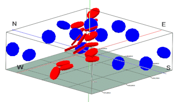
This program reads XYZ locations, bearing and dip angle measurements from the datasheet, and represents them in 3D space as oriented disks. These disks may represent fractures or other oriented planar features.
Menu Options
Step-by-Step Summary
- Rules & Filters: Use the buttons at the top of the window to apply filters and rules for this program. (More info)
- Spatial Filter: Filter the input data for the 3D disks based on XYZ location. This will also filter the data to be displayed in striplogs, if activated, based on spatial location.
- Time Filter: Filter any T-Data or Aquifer data in striplogs, if activated.
- Stratigraphic Rules: Apply stratigraphy rules for Stratigraphy data in striplogs, if activated.
- 3D Log Design
If you decide to include logs with this diagram ("Striplogs" setting, below), click on this button at the top of the window to set up how you want the 3D logs to look.
See Visible Item Summary and Using the 3D Log Designer for details.
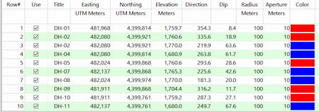
- Data Columns: These prompts tell RockWorks which columns in the current datasheet contain the input data.
Click on an existing name to select a different name from the drop-down list. See a sample layout below.
- X (Easting): Column that contains the X or Easting coordinates for the sample locations.
These can be Eastings in meters or feet, decimal longitudes, etc. See Defining your Datasheet Coordinates for more information.
- Y (Northing): Column that contains the Y or Northing coordinates for the points.
- Z (Elevation): Column that contains the elevations where the measurements were taken and where the disks should plot. Be sure you've defined the elevation units in the column heading.
- Direction: Choose the column that lists the direction, in azimuth degrees, for the strike or dip direction of the disk. Use the Directionality settings, below, to define what the bearings represent.
- Dip Angle: Choose the column that lists the dip angle. Note: For planar data, horizontal is considered to be zero, and dipping straight down is entered as 90.
- Title: Choose the column in the datasheet, if any, that lists the name or title to be plotted next to each disk.
- Directionality: Choose how the planar data are recorded in the datasheet.
- Declination
- Magnetic Declination Correction: Enter any declinaton correction as described in the program dialog.
- Azimuths (Direction) Represent...
- Inclination (Dip) Direction: Choose this option if the Direction measurements, defined in the column above, represent the dip direction of the disks.
- Strike Direction: Choose this option if the Direction measurements represent strike bearing of the disks. This assumes a right-hand rule whereby the dip direction is 90 degrees clockwise from the strike bearing.
- Color: The color of the disks can be defined as fixed or variable.
- Uniform: Choose this to plot all of the disks using the same, user-defined color. Click the color box to choose the color for all of the disks.
- Variable (Defined by Column): Choose this option to plot each disk using the colors which are listed in the datasheet.
- Color Column: Select the name of the column in which the colors are listed.
- Radius: The radii of the disks can be defined in one of two ways:
- Uniform: Choose this option to plot all of the disks using the same, user-defined radius setting.
- Radius: Enter the radius for all disks in your output units.
- Variable (Defined by Column): Choose this option to plot each disk using the radius setting which is defined within the datasheet.
- Column: Select the column in which the disk radii are listed. Be sure you've defined the data units (e.g. feet or meters) in the column heading.
- Multiplier: To universally scale the disks up or down, you can enter a value other than "1" which, when multiplied by the declared radius values, will determine the disk size.
- Aperture: The thickness of the disks can be defined in one of two ways:
- Uniform: Choose this to plot all disks at the same thickness.
- Aperture: Enter the thickness for all disks, in your output units.
- Variable (Defined by Column): Choose this option to plot each disk using thickness values which are listed within a column in the datasheet.
- Column: Select the column in which the disk thicknesses are listed. Be sure you've defined the data units (e.g. feet or meters) in the column heading.
- Multiplier: To universally scale the disks to be thickner or thinner, you can enter a value other than "1" which, when multiplied by the declared aperture values, will determine the disk thickness.
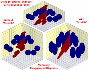
- Stretch: Check this item if you want the dip angles of the disks to change as the vertical exaggeration changes while still honoring the relative spatial relationships. Leave this un-checked if the disk angles should remain constant.
-
- Other 3D Diagram Options
Use these checkboxes to append other layers to your 3D scene.
Click each tab to set up the 3D diagram layers (images, infrastructure, reference cage, etc.).
! If you are including Striplogs, be sure to click on the 3D Log Design button at the top of the window to define the log appearance.
- Output Options
- Save Output File: Check this to assign a name for the 3D scene in advance, rather than displaying it as Untitled.
- Automatic: Choose this option to have RockWorks assign the name automatically. It will use the name of the current program plus a numeric suffix, plus the ".Rw3D" file name extension.
- Manual: Choose this option to type in a name of your own for this RockPlot3D file.
- Display Output: Check this option to have the resulting scene displayed in RockPlot3D once it is created.
- Access the RockWorks Datasheet program tab.
- Create a new datasheet and enter/import your locations and dip-direction/dip-angle data into the datasheet.
Or, open one of the sample files and replace that data with your own. See Data Layout for datasheet examples.
! Click the Example button at the top of the window to load a sample file that is installed with the program.
This example illustrates the sample file "\Documents\RockWorks Data\ Samples\Strike_and_Dip_3D_01.rwDat".
- Select the Utilities | Planes | 3D Strike & Dip Disks menu option.
- Enter the requested program settings, described above.
- Click the Continue button to proceed.
The program will read the indicated XYZ location coordinates and plot a disk at the selected dip direction and angle, using the fixed or variable size and color settings you specified. If requested, the diagram will be displayed in a RockPlot3D tab in the program window.
- You can adjust any of the settings in the Options tab and click the Contiue button to regenerate the display.
- View / save / manipulate / print / export the scene in the RockPlot3D window.
 Back to Planes Menu Summary

RockWare home page