RockWorks | ModOps | Grid | Directional | Stereonet
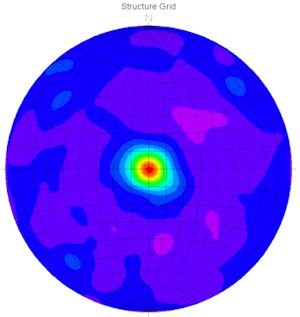
This program reads a grid model and computes the changes in Z-values or elevations between neighboring nodes (= slope), noting the direction of steepest change (= "aspect"). It then creates a stereonet diagram to summarize the directionality of the aspect bearings (dip direction) and the steepness of the slopes (dip angle).
Note: This program requires that a RockWorks surface (grid) model already exist.
Menu Options
Step-by-Step Summary
- Grid - Stereonet
- Other 2D Files
Check this option to include existing RockWorks diagrams as layers with this diagram.
Click on this tab to select the existing diagrams (.Rw2D files) to be included. (More info)
- Peripherals
Check this option to include various peripheral annotations with your diagram. Options include titles, north arrows, and more.
Click on this tab to activate the items and establish their settings. (More info)
- Border
Check this option to include a solid line border around the entire diagram image.
Click on this tab to specify the line style, thickness, and color.
- Output Options
- Save Output File: Check this to assign a name for the diagram in advance, rather than displaying it as Untitled.
- Automatic: Choose this option to have RockWorks assign the name automatically. It will use the name of the current program plus a numeric suffix, plus the ".Rw2D" file name extension.
- Manual: Choose this option to type in a name of your own for this file.
- Display Output: Check this option to have the resulting diagram displayed in RockPlot2D once it is created.
- Be sure you have a RockWorks grid model already created, for input into this program.
- Select the ModOps | Grid | Directional | Stereonet menu option.
- Enter the requested menu settings, described above.
- Click the Process button to continue.
The program will read the input grid model, compute the slope and aspect for each node, and determine the dip direction and slope angle for each node. It will then generate a stereonet diagram to represent the distribution of the node directionality. The stereonet diagram will be displayed in a RockPlot2D tab in the Options window.
- You can adjust any of the settings in the Options window (input grid model name, diagram settings, etc.) and then click the Process button again to regenerate the diagram.
- View / save / manipulate / export / print the diagram in the RockPlot2D window.
 Back to Grid Menu Summary

RockWare home page