RockWorks | ModOps | Solid | Extract Grids | Solid Layer -> Grid
This program is used to pull out a 2-dimensional grid file from an existing real number or Boolean solid model file. The grid file can be extracted from any horizontal (constant Z) or vertical (constant Y or X) layer in the original solid model. The program will read the input solid model file and extract the requested layer. The node values will be stored in a 2-dimensional grid file under the file name you requested.
Note: This tool requires that a RockWorks Boolean OR real number solid model already exists.
Feature level: RockWorks Basic and higher
Menu Options
Step-by-Step Summary
- Input/Output
- RockWorks Solid Model File (Input): Click to the right to browse for the name of the existing solid model (.RwMod file) that the program is to read. This may be a real number solid model or a Boolean (true/false) solid model.
- RockWorks Grid Model File (Output): Click to enter the name to assign to the new grid file (.RwGrd) that the program will create.
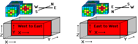
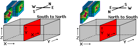
- Slice Orientation: These settings determine the orientation of the solid model slice that will be stored as a grid file. Choose from the following:
- Slice Selection
Click here to define how you want to define the location for the extracted grid.
- Select Interactively During Processing: Click here to have the program display a window, after you click the Continue button, where you can interactively select the location for the extracted slice.
- Preselect: Choose this to define the location in advance. If you are including this program in a Playlist or Command script, you'll need to pre-select the location. Enter that elevation (if horizontal), Y coordinate (if vertical, east/west), or X coordinate (if vertical, north/south) into the prompt. These are actual elevation or coordinate numbers, not solid model node layer counts.
- Create 2-Dimensional Grid Diagram: Insert a check here to create a 2D map of the output grid model. Click on this tab to set up the 2D map layers (bitmap, symbols, labels, line contours, color-filled contours, labeled cells, etc.).
! Don't request map symbols or labels if you don't have any data loaded into the Utilities datasheet at this time.
- Output Options: Use these settings to define whether the output graphic is to be saved (or displayed as "untitled"), how the file should be named, and whether it is to be displayed after it is created. It also offers export options. (More info)
- 3D Grid Diagram: Insert a check here to create a 3-dimensional image of the output grid model. Click on this tab to set up the 3D map layers (surface style, colors, perimeter, reference cage, etc.).
- Output Options: Use these settings to define whether the output scene is to be saved (or displayed as "untitled"), how the file should be named, and whether it is to be displayed after it is created. It also offers export options. (More info)
- Be sure you have an existing solid model already created, for input into this program.
- If you want to include your control point symbols on a 2D map, you'll need to create or open datasheet containing a listing of these X and Y locations.
! Tip: Use the Borehole Manager's File | Transfer | Locations -> Datasheet to transfer a listing of your borehole location data to the datasheet.
- Select the ModOps | Solid | Extract Grids | Solid Layer -> Grid menu option.
- Enter the requested menu settings, described above.
- Click the Continue button to proceed.
RockWorks will scan the input solid model file and display the number of layers in the selected slice direction. For example, if you've selected a horizontal slice, the program will display the top to bottom layers in the model and their Z (elevation) coordinates. Or, if you have selected a north-south vertical slice, it will display the slices and their X coordinates.
- Click on the layer you wish to extract, to highlight it, and click OK to continue.
Note: If you expect to re-insert this grid into the solid model at a later time, write down the layer orientation and coordinate; they are easy to forget.
The program will read the input solid model file and extract the requested layer. The node values will be stored in a 2-dimensional grid file under the file name you requested.
If you requested a 2D map, it will be displayed in a RockPlot2D tab in the Options window.
- You can adjust any of the settings via the main Options tab to the left, and then click the Continue button again to regenerate the grid model and diagram.
- View / save / manipulate / print the diagram in the RockPlot2D and/or RockPlot3D window.
 Back to Solid Menu Summary

RockWare home page