RockWorks | Borehole Manager | Stratigraphy | Model
Use this program to:
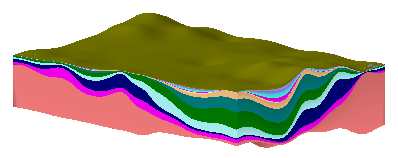
The surfaces and panels will be color-coded based on the formation's background color in the Stratigraphy Types Table. The surface grid models will be stored in the project folder. The completed diagram will be displayed in a RockPlot3D window, with volume and mass of each formation noted.
The program offers optional creation of a 3D solid model (.RwMod file) representing the stratigraphy surfaces layered from the bottom up, for use with other analysis tools.
Feature Level: RockWorks Standard and higher
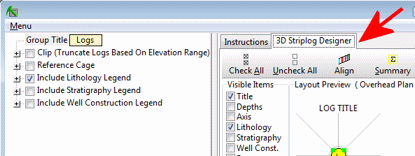
Menu Options
Step-by-Step Instructions

! To get a high-resolution solid model, be sure your project dimensions are set with Z-nodes spaced closely enough to adequately represent surface details.


If Interpolate Surfaces is turned on, the program will use the selected gridding algorithm to create grid models of the surfaces and bases of the formations listed in the Stratigraphy tabs, storing the models in the current project folder. The grid file names are assigned automatically, based on the formation: "formation_top.RwGrd" and "formation_base.RwGrd". Two grid models will be created for each formation.
If Save Numeric Model is turned on, the program will initialize the solid model using the current project dimensions. It will then "insert" each gridded formation into the solid model, by assigning the voxels between the surfaces the integer "G" value listed in the Stratigraphy Types Table. The program will store this stratigraphic model file in the project folder using the file name you requested.
The formation grid models will be displayed in a RockPlot3D tab in the Options window, with each formation represented by a lower and upper surface and enclosing sides. If logs were requested, they will be added to the view.
Tips: Once displayed in RockPlot3D, you can expand the stratigraphy model item in the data pane to see the formation names. Expand the individual formations to see grid models for the base and the surface, and computed formation volume and mass (if available).
See also: Manually Building 3D Stratigraphic Diagrams for information about building diagrams from existing grid models (filtered, imported, etc.)
![]() Back to Stratigraphy Menu Summary
Back to Stratigraphy Menu Summary
![]()