Introduction
Step-by-Step Summary
Notes
Introduction
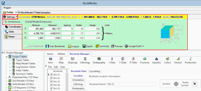
What they are: The Grid & Model Dimensions (aka Output Dimensions) are really important in RockWorks when you are working in the Borehole Manager or Utilities. They define for the program:
- The boundary coordinates of your project area. The program will use these to know how big your project "space" is, and will use this to scale all of your map and diagram components - 2D text, log widths, etc.
- The dimensions of your models: 2D grid models (.rwGrd) and 3D solid models (.rwMod) - their extents and node density, which affect interpolation quality and processing time.
- The type of coordinates - local or global, and if the latter the coordinate system (e.g. UTM or State Plane).
- The units these coordinates represent (e.g. local feet or UTM meters).
If you are working in the Borehole Manager, the Grid & Model Dimensions must represent the same coordinate system as your borehole data. The coordinate units (feet or meters) can be different than your input data coordinates - RockWorks can convert them during mapping and modeling.
If you are working in the Utilities, your datasheet can contain spatial coordinates in any of the supported coordinate systems; RockWorks will convert them during mapping and modeling. For example, if your map locations are entered into the datasheet in longitude and latitude coordinates, they'll be converted to your output UTM Meters to build your map.
When they are established:
- The coordinate system (UTM v. State Plane v. local) and the units (feet or meters) for the Grid & Model Dimensions are established when you create a new project.
- The actual min-max coordinate values can be established at any time before/during/after the entry of your data.
Where they are displayed: The current Grid & Model Dimensions and coordinate system are displayed in a pane above the Utilities and Borehole Manager program tabs, expandable and collapsible via the "Settings" button.
The Grid & Model Dimensions can also be accessed via the Adjust Output Dimensions button in many of the program's menus, shown below.

Where they are stored: The Grid & Model Dimensions are stored in the current project database. Though these dimensions can be overridden during model and diagram creation, we generally recommend that you utilize these dimensions for your grid models, solid models, and diagram annotations for ease and consistency. For example, all the project grid models must have the same dimensions and node densities if you wish to perform any mathematical or filtering operations with them. The same holds true for solid models.
For new projects the dimensions will default to a range of 0 to 100 along all axes.
Step-by-Step Summary
- If you know the minimum and maximum coordinates for your project, you can type them right in to the Grid & Model Dimensions prompts.
- OR - If you don't know them off the top of your head, you can have the program scan your data to determine the coordinate extents:
- Borehole Manager: Click the Scan Boreholes button. In the displayed window...
- Scan All Boreholes: Choose this option if RockWorks should scan all of the boreholes in the database to determine the project extents.
- Scan Only Enabled Boreholes: Choose this option if RockWorks should scan only the enabled boreholes - those with check-marks by their names - to determine the project extents. This is a good option if the disabled holes are outside the desired working area or contain incomplete data.
- Other Options: The Scan Boreholes window contains other settings which determine how the project extents and node spacing will be initially determined. (More.)
- RockWorks Utilities: Click the Scan Datasheet button. In the displayed window...
- X-Column: Choose the column in the current datasheet that contains the X-Coordinates (east-west) upon which the output dimensions are to be based.
- Y-Column: Choose the column that contains the Y-Coordinates (north-south) upon which the output dimensions are to be based.
- Z-Column: Choose the column that contains the elevation coordinates upon which the output dimensions are to be based (if you choose to scan for XYZ dimensions).
- Other Options: The Scan Datasheet window contains other settings which determine how the project extents and node spacing will be initially determined. (More.)
- Review: Review the scanned settings to be sure they make sense. THIS IS REALLY IMPORTANT.
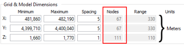
Minimum and Maximum Dimensions - Spacing Settings - Number of Nodes
- Minimum and Maximum Dimensions: These boundary coordinates can be hand-entered or determined by the program via the Scan Boreholes button.
- X-Minimum and X-Maximum: These coordinates define the western and eastern map extents of your project.

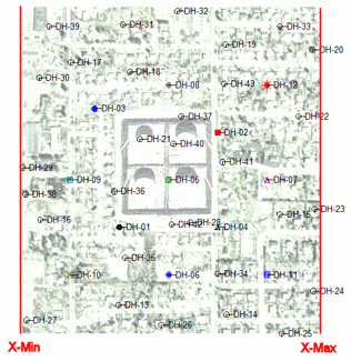
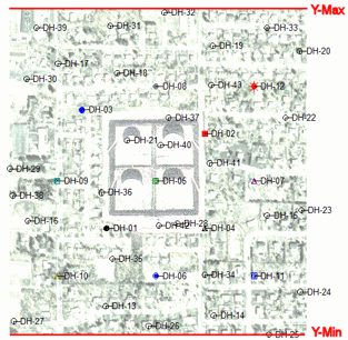
- Y-Minimum and Y-Maximum: These coordinates define the southern and northern map extents of your project.

- Z-Minimum and Z-Maximum: These coordinates define the elevation extents of your project.


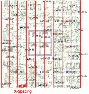
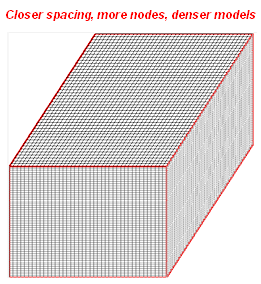
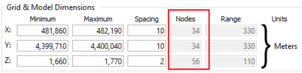
- Spacing Settings: These settings pertain to interpolated models only. They represent the spacing between nodes along each axis and (hence) the density of the models the program will create. LOOK AT THESE NUMBERS. Node density affects the quality of the model and the time necessary to generate it.
The X-Spacing will define how far apart grid and solid model nodes will be from west to east. It is declared in your map units.

The Y-Spacing will define how far apart grid and solid model nodes will be from south to north. It is declared in your map units.


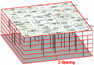
The Z-Spacing will define how far apart grid and solid model nodes will be from the lowest elevation to the top elevation in the project. It is declared in elevation units. (Which should, incidentally, be the same units – feet or meters – as your X,Y map units.)

-
Number of Nodes: These prompts display the number of nodes that will be generated along each axis. These are computed automatically, based on the dimensions divided by the spacing. You cannot edit the node settings; to adjust the density, edit the spacing.
Notes:
- If the default number of X and Y nodes is too high or too low, you can either hand-edit the spacing value(s) or adjust the Horizontal Resolution (under the Borehole or Datasheet scan options) and re-scan.
- If the default number of Z (elevation) nodes is too high or low, you can hand-edit the spacing value or adjust the Vertical Resolution (under the Borehole or Datasheet scan options) and re-scan.
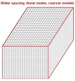
- Denser is not always better. You might create less-dense models on trial runs and increase the density only if you feel the detail of the data is not being represented.
- Keep in mind that a solid model with 50 x 50 x 50 nodes (125,000 total) requires one-eighth the computations of a 100 x 100 x 100-node model (1 million nodes)
- See also: How Dense is Dense Enough? (Output Dimensions Tips)

RockWare home page