RockWorks | ModOps | Solid | Filters | Merge
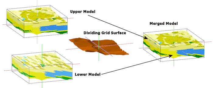
This program reads two existing solid models (.RwMod files) and a grid surface (.RwGrd file), and creates a new model in which the upper portion is based on one of the originals, and the lower portion is based on the other.
This feature allows you to model different parts of your geology using different techniques. In the graphic example above, the upper lithology model represents regular (horizontally-biased) interpolation, and the lower was generated with a regional tilt. Merging these models using a surface delineating the discontinuity permits the model to show the two different techniques.
! The solid models and the grid model must have the same dimensions.
Feature Level: RockWorks Basic and higher
Menu Options
Step-by-Step Summary
- 3D Log Design
If you decide to include logs with this diagram (3D Solid Diagram | Striplogs), click on this tab at the top of the window to set up how you want the 3D logs to look.
See Visible Item Summary and Using the 3D Log Designer for details.
- Rules & Filters
Use these tabs at the top of the window to apply spatial filters, time/date filters, or stratigraphic rules to data being displayed in your 3D striplogs. (More info)
- Options
- Input
- Solid Model That Contains Upper Nodes: Click to the right to browse for the name of the existing RockWorks solid model file (.RwMod file) whose nodes are to be used for the upper part of the output model.
- Grid Model Used To Define Upper/Lower Demarcation: Click here to browse for the name of the existing grid model to be used as the dividing grid.
- Solid Model That Contains Lower Nodes: Click to browse for the name of the existing solid model file (.RwMod file) whose nodes are to be used for the lower part of the output model.
- Output: Merged Model: Click to the right to type in a name for the output solid model file (.RwMod) which will contain the merged model.
- 3D Solid Diagram
Check this box to display the output solid as a 3D voxel or isosurface diagram at this time.
Click this tab to set up the 3D solid layers (isosurface, voxels, reference cage, etc.).
- Output Options: Use these settings to define whether the output scene is to be saved (or displayed as "untitled"), how the file should be named, and whether it is to be displayed after it is created. It also offers export options. (More info)
- Select the ModOps | Solid | Filters | Merge menu option.
- Enter the requested menu settings, described above.
- Click the Continue button to proceed.
RockWorks will load the input solid model files, determine the nodes in the Top Model that lie above the divider grid, and determine the nodes in the Base Model that lie below the divider grid. Those node values will be copied to the output model.
If you requested a diagram, it will be displayed in a RockPlot3D tab in the Options window, using the requested display type.
- You can adjust any of the input or diagram settings via the Options tab to the left, and then click the Continue button again to regenerate the display.
- View / save / manipulate / print / export the model in the RockPlot3D window.
 Back to Solid Menu Summary

RockWare home page