RockPlot2D | Draw | Line Types | Polyline
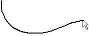
Use the Polyline menu command or toolbar button to draw a multiple-segmented line on an existing RockPlot2D image. See the Lines option for inserting a single-segment line.
Step-by-Step Summary
Options
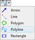
- Select the Draw | Line Types | Polyline menu item, or click on the Draw | Polyline button at the top of the screen
 .
.
The Polyline button is available in the Draw | Line Types drop-down menu.
The program will be in "Draw Polyline" mode, as noted at the bottom of the screen.
- Position the pointer in the graphic window where one endpoint of the polyline is to be placed, and click and release the left mouse button. (See the Snap options described below.)
- Drag the cursor in any direction and the line will be drawn between the starting point and the current cursor position.
- Click the left mouse button to insert the next vertex.
- Drag and click as above to draw additional vertices.
- Double-click the mouse button to terminate the polyline.
- To turn off the Draw Polyline mode, click the Draw Polyline X button at the bottom of the window, or press the Shift+Escape keys, or click the Edit button
 .
.
- To snap the polyline vertices:
- Hold down the Ctrl key while drawing to snap the next vertex to any location on the nearest line.
- Hold down the Shift key while drawing to snap the next vertex to the nearest vertex on the nearest object.
- Hold down both the Ctrl + Shift keys while drawing to snap the next vertex to the nearest Smart Snap point.
- To edit the polyline's characteristics (color, style, etc.):
- Click the Edit button at the top of the window
- Double-click on the polyline, or right-click on it and choose Properties.
- Adjust the polyline's settings. See Polyline Attributes for information.
- To edit the position of any of the polyline's vertices:
- Click the Edit button at the top of the window
- Right-click on the polyline and choose Edit Vertices.
- Follow the instructions outlined under Editing Vertices.
- To save the polyline to an XY Coordinates table, for use in scripting cross-section creation:
- Click the Edit button at the top of the window
- Right-click on the polyline and choose Copy to XY Coordinates Table.
- To save the polyline to an XY Pairs Table, for use in scripting fence diagram creation:
- Click the Edit button at the top of the window
- Right-click on the polyline and choose Copy to XY Pairs Table.
- To save the polyline to a Fault table, for use in creating faulted grid models:
- Click the Edit button at the top of the window
- Right-click on the polyline and choose Copy to Faults Table. Assign the fault a name, specify 2D or 3D, and assign the fault parameters.
 Back to Drawing Tools

RockWare home page