- Size and Drag: This setting controls the color of the handles that are displayed when a graphic item is selected in the RockPlot2D window. Note that the program will change the color of the handles if the item is displayed against a same-color background, such as a color-filled contour map zone.
- Vertex: This setting controls the color of the handles that are displayed on polygons or polylines when in Edit Vertex mode.
- Dynamic Pattern Scaling (Automatic): This is the default setting. With this, RockPlot2D will display all images that contain patterns (such as cross-sections) using the pattern densities stored in the image itself.
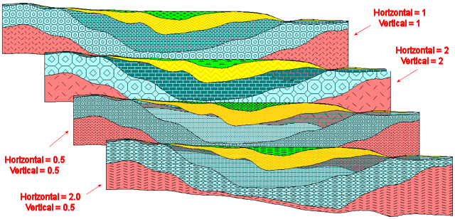
- Fixed Pattern Scaling (Manual): Choose this option if you don't like the default pattern scaling. It allows you to enter a scalar for both the horizontal and vertical axes. This can be helpful if the patterns overall are simply too coarse or dense, of if you are displaying a cross-section at a very large vertical exaggeration and the patterns are being stretched.
- Horizontal Scalar: Type in the value by which the existing pattern densities will be multiplied. A value > 1 will make the pattern blocks larger (less dense) along the horizontal axis of the diagram.
- Vertical Scalar: Type in the value by which the existing pattern pattern densities will be multiplied along the vertical axis of the diagram.
! These do NOT affect the drawing tools (Draw menu).
- Area: These settings will affect the Measure | Area tool.

- Choose the line style and color for the polygon(s) that will be drawn on the screen.
- Choose the number of decimal places for the area computations.
- Bearing: These settings will affect the Measure | Bearing tool.

- Choose the line style and color for the line(s) that will be drawn on the screen.
- Choose the number of decimal places for the bearing computations.
- Distance: These settings will affect the Measure | Distance tool.

- Choose the line style and color for the line(s) that will be drawn on the screen.
- Choose the number of decimal places for the distance computations.
- Perimeter: These settings will affect the Measure | Perimeter tool.

- Choose the line style and color for the polygon(s) that will be drawn on the screen.
- Choose the number of decimal places for the perimeter computations.
- Points: These settings will affect the Digitize | Point tool.

- Choose the color and size for the symbol(s) that will be drawn on the screen. Size is expressed as a percent of map width; a setting of "1" will create very small symbols, and a setting of "10" quite large symbols. The symbol style is hard-wired to be small "X"s.
- You can also declare the number of decimal places for the X,Y coordinates recorded for the digitized point locations.
- Lines: These settings will affect the Digitize | Line tool.

- Choose the line style and color for the line(s) that will be drawn on the screen.
- Choose the number of decimal places for the X, Y coordinates recorded for the digitized line endpoints.
- Polylines: These settings will affect the Digitize | Polyline tool.

- Choose the line style and color for the polyline(s) that will be drawn on the screen.
- Choose the number of decimal places for the X, Y coordinates recorded for the digitized polyline vertices.
- Polygons: These settings will affect the Digitize | Polygon tool.

- Choose the line style and color for the polygon(s) that will be drawn on the screen.
- Choose the number of decimal places for the X, Y coordinates recorded for the digitized polygon vertices.
- Image to Clipboard Options: Choose the image displayed as the view that will copy to the clipboard, or choose to copy the entire canvas.
-
- Choose additonal settings for Removing Whitespace and Adding Inner and Outer Borders; specify each border color and thickness that will be drawn on the screen.
- Default Start Up Mode is used for selecting the initial cursor action when working with the drawn image.
-
- Choose Zoom to have the cursor zoom in on the image created with the first click.
- Choose Select to use the mouse as a cursor to select items on the image with the first click.
![]() Back to File menu
Back to File menu
![]()