RockPlot2D | Measure | Bearing
Use the Bearing menu command or toolbar button to measure the bearing of a line drawn on the RockPlot2D screen display. The computed bearings are displayed in the window's data pane.
- If necessary, open the diagram for which you wish to compute bearings (see Opening Plot Files) or click in the current RockPlot2D window containing the diagram.
! It’s important that this image be created at equal units horizontally and vertically for the bearing computations to be accurate. The image does not, however, need to be displayed in RockPlot2D at equal scales (vertical exaggeration can be < or > 1).
- Select the Measure | Bearing menu item, or click on the Measure | Bearing button at the top of the screen
 .
.
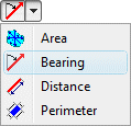
The Bearing button is available in the Measure drop-down menu.
The program will be in "Measure Bearing" mode, as noted at the bottom of the screen.
- Click on the starting point of the line.
- Click on the ending point of the line. (Note that endpoint order is important in determining bearing.)
- The program will display the line on the screen display, and compute its bearing. The bearing, in azimuth degrees with 0 = north, will be displayed in the data window to the right.
- Repeat this process if you wish to digitize another line for bearing computation.
- To terminate the Measure Bearing mode, click the Measure Bearing X button at the bottom of the window, or click the arrow button
 at the top of the window, or press the Shift+Escape keys.
! If you recreate or close the RockPlot2D window before copying the data to the clipboard, it will be lost. The data is not stored in the Rw2D file.
- Use the Options | Export | Windows Clipboard menu option (above the data pane) to copy the contents of the data window to your computer's Clipboard, for pasting into any document. See The Data Window.

RockWare home page