RockWorks | Utilities | Faults | Multiple Dip Lists -> 3D Ribbons
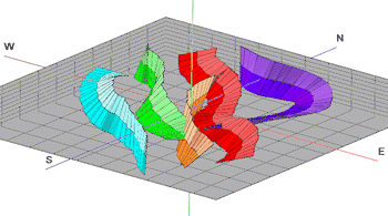
This program reads a series of individual RwDat files, each of which contains a list of dip data (XYZ coordinates, dip direction, and dip angle), fits a smooth curve to each list of points, in the order that they're listed, and then projects a ribbon-like surface up-dip and/or down-dip from each curve.
! The program assumes that each .RwDat file, for each ribbon, is formatted exactly the same. The source columns in the input files are assumed to be those which are currently stored for the Single Dip List -> 3D Ribbon program, where the XYZ coordinate columns, dip direction, and dip angle are defined. We recommend you run a few of the input datasheet files through that option to be sure the column selections are correct, coordinate and unit definitions are correct, general diagram settings are to your liking, etc.
See also: Plotting 3D Dip Ribbons - Single, Creating a 3D Fault File - Multiple Faults
Menu Options
Step-by-Step Summary
Menu Options
- Input Columns: The prompts along the left side of the window tell RockWorks which columns in the input datasheet contain what data.
Click on an existing name to select a different name from the drop-down list. See a sample data layout below.
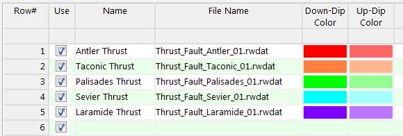
- Group Name: Column that contains the name for each fault.
- File Name: Column that contains names of the RwDat files which contain the individual fault definitions.
! Each of the fault files listed here must have the same layout. See the VERY IMPORTANT NOTE below.
- Down-Dip Color: Column that contains the color for the down-dip fault panels.
See Column Types for information about defining color blocks in the datasheet
- Up-Dip Color: Choose the column that contains the color for the up-dip panels.
- Distance Increment: This setting controls how finely the dip ribbons will be subdivided, and is expressed as distance in your map units.
- Project Down-Dip: Insert a check here if you want the panels to be projected down-dip from the fault polylines.
- Down-Dip Projection Distance: Click here to type in the distance, in your project units.
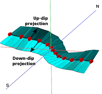
- Project Up-Dip: Insert a check here if you want the ribbon panels to extend up-dip from the fault polylines.
- Up-Dip Projection Distance: Click here to type in the projection distance, in your project units.
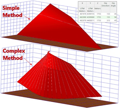
- Method: Choose the detail for your ribbons:
- Simple (Endpoints only): Select this to draw the fault panels between the two endpoints only. This really comes into play when creating fault files for modeling and the the faults can be treated as planes rather than complex surfaces, in order to significantly speed up the modeling. Should you use Simple for your Fault File, you can choose that option here also for the ribbon diagrams which you can append to your faulted model diagram.
- Complex (Subdivide and Smooth): For any given list of dip points (including lists with just two points), intermediate points will be interpolated in order to reduce the angularity of the fault surface. Although this creates more accurate and aesthetically pleasing fault surfaces, it can significantly increase the amount of time required to create block models that use the fault files.
-
- Drawing Style:
- Lines: Choose the color and thickness for the ribbon panel outlines. A thickness of "1" creates fairly thin lines, and "5" fairly thick.
- Panels: Choose from Solid Color (filled) or Wireframe. If you choose Solid, the Down-Dip and Up-Dip colors specified in the datasheet will be used for the fill.
Step-by-Step Summary
- Access the RockWorks Utilities program tab.
- Create a new datasheet and enter/import your list of dip-direction/dip-angle file names into the datasheet.
Or, open one of the sample files and replace that data with your own. (In the Samples folder, an example file = "\RockWorks17 Data\ Samples\Dip_Ribbons_01.RwDat", shown here.)
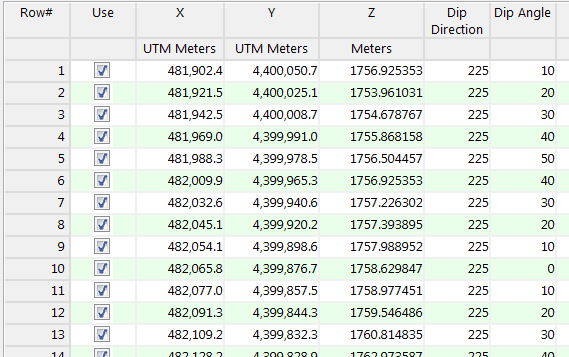
Each of the RwDat files listed in the File Name column should be formatted the same, such as the following example (from the Samples folder, "\RockWorks17 Data\ Samples\Thrust_Fault_Antler_01.RwDat").
VERY IMPORTANT NOTE: RockWorks will assume that the input columns in all of the listed RwDat files are those which are defined in the Faults | Single Dip List -> 3D Ribbon menu option. So, it's a good idea to open one of the listed RwDat files, set up the Input Columns in the Single Dip List program (the "child" program), then run the Multiple Dip Lists ("parent") program.
The minimum number of points required to create each fault is 2.
- Select the Faults | Multiple Dip Lists -> 3D Ribbons menu option.
- Enter the requested menu settings, described above.
- Click the Process button to continue.
The program will read the indicated XYZ location coordinates from each listed RwDat file and create a ribbon of oriented panels at the selected dip directions and angles, using the defined settings. The diagram will be displayed in a RockPlot3D tab in the Options window.
- You can adjust any of the options along the left and click the Process button to regenerate the display.
! Each time you click the Process button, the existing display will be replaced.
- View / save / manipulate / print / export the image in the RockPlot3D window.
Tip: If you get an error that RockWorks cannot read the data properly from the listed .RwDat files, be sure that you've defined the input column names properly in the Single Dip List -> 3D Ribbon program: Open one of the listed files, choose that menu option, and select the required input column names.
See also: Creating a 3D Fault File - Multiple Faults
 Back to Faults Menu Summary

RockWare home page