RockWorks | Graphics | Animate | Solids -> 3D Isoshell Animation
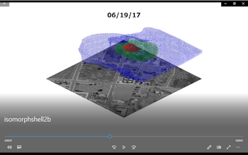
Use this program to read two solid models or a list of solid model names, and create 3D isosurface animations based on the model changes over time. One, two, or three different concentration levels can be represented in the "isoshells"; choose solid or wire-frame and opacity. These animations may be saved to a variety of video formats. This is commmonly known as "solid morphing".
See also
Create a 3D Voxel/Isosurface Animation of Time-Based Solid Models
Display an Existing Solid Model as a Nested 3D Isosurface Diagram
Feature Level: RockWorks Basic and higher
Menu Options
Step-by-Step Summary
- Input Solids
Use these settings to define whether the morph is based on two solid models or on multiple models.
- Two Models: Click this radio button if the morph sequence is to be based on two existing solid models.
- Initial Model: Click to browse for the name of the existing solid model (.RwMod file) that is to represent the start of the morph.
- Date: Use this box to define the date represented by the starting model.
- Final Model: Click to browse for the name of the existing solid model file to be the end of the morph sequence.
! This model must have the same dimensions and number of nodes as the starting model.
- Date: Choose the date represented by the ending model.
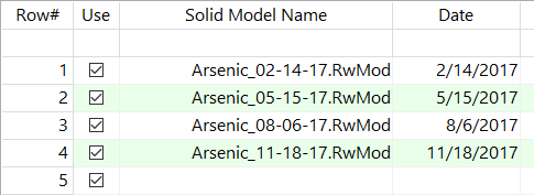
- List of Models (Datasheet): Click in this button if the morph sequence is to be based on more than two existing solid models. This requires that you have the solid model names (.RwMod files) listed in a column in the current datasheet, along with their sampling dates.
- File Name: Select the name of the column in your datasheet which lists the names of the solid models to be morphed.
- Date Column: Select the name of the column in your datasheet which lists the date represented by each model.
- Include Time Within Dates: Check this item if the dates in the Datasheet include time of day and this is to be included in the morph.
- Transitional Frames: Here you define the number of intermediate solid models to morph between the beginning and ending model (if you are morphing only two) or between each of the listed solid models (if you are morphing from a list) for generating the 3D images. If you choose "10" for example, there will be 10 intermediary voxel/isosurface diagrams created between each input model. Note that RockWorks does not store the intermediate solid models, just the graphic representations of them.
- Thresholds:
Click on this tab to define the G value thresholds for each isoshell. These provide the means of limiting the view to a specific concentration, or set of concentrations, in the models. List the highest cutoff value at the top (the smallest isosurface), and the lowest cutoff at the bottom (largest isosurface). You can enter up to 6 thresholds, for 6 different isolevels within the model.
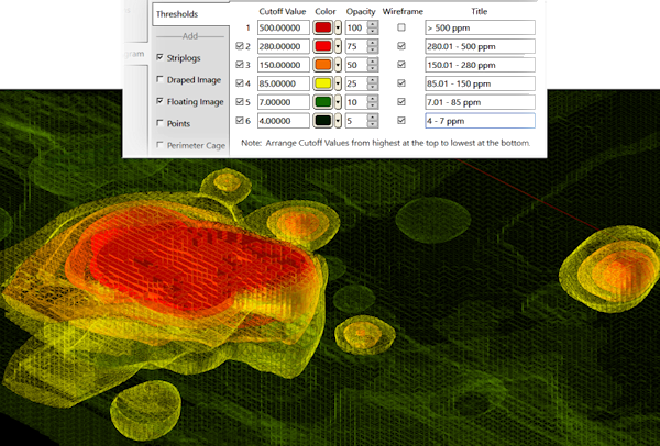
- Cutoff Value: Enter the value in the input solid model at which the isosurface "skin" is to be drawn.
- Color: Choose a color for that isolevel.
- Opacity: Set the opacity for that isolevel. Be sure to set the isolevels at the bottom of the table to < 100% opacity so that the smaller isosurfaces inside will be visible in RockPlot3D.
- Wireframe: Check this box if that isolevel is to be drawn as a wireframe rather than as a solid skin.
- Title: Enter a title for each isolevel. This will be used to label the item.
- Striplogs: Append striplogs to your 3D scene. (More info)
! If you are including Striplogs, be sure to click on the 3D Log Design button at the top of the window to define the log appearance.
- Clip: Check this if you want to restrict the logs to a particular spatial area. (More info)
- T-Data Only: If checked, striplogs within the animations will be filtered such that only the logs with T-Data that was sampled during the model date interval will be shown. For example, when the animation is showing the 2016 plume, only the wells sampled in 2016 will be shown. This feature is based on the observation that most projects start with just a few monitor wells. Additional wells are then added as the plume migrates. This capability also provides visual cues as to when a plume artificially contracts based on a new well rather than an actual geochemical contraction.
- Other 3D Diagram Options
Use these checkboxes to append other layers to your 3D scene.
Click each tab to set up the 3D diagram layers (images, infrastructure, reference cage, etc.).
- Output Options: Use these settings to define the animation output file type and display settings. (More info)
- Access the RockWorks Datasheet program tab.
- If you will be morphing two RockWorks solid models, be sure these .RwMod files already exist in the project folder.
If you will be morphing 3+ models, open or create a datasheet that lists one column with the names of the RockWorks solid model files (.RwMod files) to be morphed, and another column listing the date each represents. The RwMod files must reside in the current project folder. The models should be listed with the first model in the sequence listed first and the last model listed last.
! Click the Example button at the top of the window to load a sample file that is installed with the program.
! The solid models to be morphed must have the same dimensions and node densities. If you are unsure, use the Solid | Statistics | Report tool to view a summary of any solid model file.
- Select the Graphics | Animate | Solids -> 3D Isoshell Animation menu option.
- Enter the program settings, discussed above.
- Be sure to review the Output Options - the image prefix you defined and the video output format.
- Click the Continue button to proceed.
The program will:
- Load the first and second solid models, and generate the selected number of intermediate models using an averaging method ((Solid A + Solid C)/2 = Solid B). It will repeat for all of the remaining models.
- Generate a 3D isosurface representation of each requested isolevel, in each model.
- Export each 3D scene to a PNG image format, storing the image files using the requested file name prefix, in the "Animation_Frames" sub-folder in your project folder.
- Generate the selected video output.
- Load the output video into the default player, if requested.
 Back to Animate Menu Summary

RockWare home page