RockWorks | ModOps | Grid | Directional | Rose Diagram
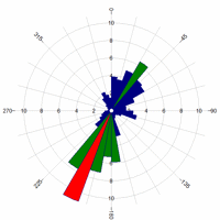
This program tool reads a grid (surface) model and computes the changes in Z-values (elevations) between neighboring nodes, noting the direction (0 to 360) of steepest change (= "aspect"). It then creates a rose diagram to summarize the directionality of the aspect bearings (dip direction) or of the corresponding structure bearings (strike direction).
Note: This program requires that a RockWorks surface (grid) model already exist.
Menu Options
Step-by-Step Summary
- Grid Name: Click to the right to browse for the name of the existing grid model (".RwGrd" file) to be analyzed and displayed as a rose diagram.
- Directionality
- Direction Represented by Rose Petals:
- Aspect (Dip Direction): Choose this option if the rose petals are to represent the direction at which the surface's grid nodes slope (= the dip direction).
- Structural Axes (Strike Direction): Choose this option if the rose petals are to represent the strike direction (= 90 degrees counter-clockwise of the aspect azimuth).
- Minimum Slope: Enter the slope, in degrees, below which the node will not be included in the rose diagram. This is a means of removing relatively flat areas in the grid model from the calculations.
- Diagram Options
Click on this tab to set up the appearance of the rose diagram. (More info.)
- Other 2D Files
Check this option to include existing RockWorks maps as layers with your map. For example, if you have a land grid map already created for your project, you can include that as a layer here.
Click on this tab to select the existing maps (.Rw2D files) to be included. (More info)
- Peripherals
Check this option to include various map peripheral annotations with your map. Options include titles, north arrows, scalebars, and more.
Click on this tab to activate the items and establish their settings. (More info)
- Border
Check this option to include a solid line border around the entire map image.
Click on this tab to specify the line style, thickness, and color.
- Output Options
- Save Output File: Check this to assign a name for the map in advance, rather than displaying it as Untitled.
- Automatic: Choose this option to have RockWorks assign the name automatically. It will use the name of the current program plus a numeric suffix, plus the ".Rw2D" file name extension.
- Manual: Choose this option to type in a name of your own for this file.
- Display Output: Check this option to have the resulting map displayed in RockPlot2D once it is created.
- Be sure you have a RockWorks grid model (.RwGrd file) already created, for input into this program.
- Select the Grid | Directional Analyses | Grid -> Rose Diagram menu option.
- Enter the requested menu settings, described above.
- Click the Process button to continue.
The program will read the input grid model, compute the slope and aspect for each node, and determine the dip direction or strike direction for each node. It will then tally the number of nodes whose direction falls within the petal groupings, and will generate a rose diagram using the requested diagram settings. The rose diagram will be displayed in a RockPlot2D tab in the Options window.
- You can adjust any of the settings in the Options window (input grid model name, diagram settings, etc.) and then click the Process button again to regenerate the rose.
- View / save / manipulate / export / print the diagram in the RockPlot2D window.
 Back to Grid Menu Summary

RockWare home page