RockWorks | ModOps | Grid | Import
This program is used to read an existing set of gridded data stored in one of the accepted formats and translate the data into a RockWorks grid file format. This tool also imports raster images (JPG or BMP) and translates them into a grid format.
Menu Options
Step-by-Step Summary
- Input/Output
- Input File: Click to browse for the name of the grid file that you wish to import into RockWorks. If you are importing a bitmap (raster) image, see below for supported file types.
- Input Format: Select the format in which the input file is stored by clicking in the appropriate radio button. Click on the item's tab to access any additional options.
- ASCII (Text): ASCII grid files consist of a list of space- or tab-delimited xyz values in which each line contains one node, also referred to as "Text" format.
- This file must also include 6 header lines that list the following:
- The minimum X coordinate
The maximum X coordinate
The minimum Y coordinates
The maximum Y coordinate
The spacing of the nodes along the X axis
The spacing of the nodes along the Y axis
- Followed by the listing of the X Y Z triplets, one for each grid node.
- Tip: Use the Grid | Export | ASCII XYZ program, with header turned on, to export an existing RockWorks grid model to an ASCII format. That output file has the same format as the ASCII input file here.
- Bitmap (Raster Image): RockWorks can import raster images and store them as grid models. The supported file types are BMP, JPG, EMF and WMF, PCX, PNG, TGA, and TIFF.
- Normalize: If unchecked, the Z-values stored in the output model will represent the colors in the input bitmap file, which can range into the millions. If checked, the input bitmap's colors will be normalized between user-specified minimum and maximum values.
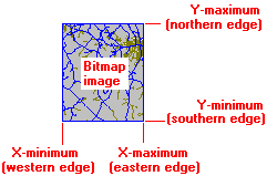
- Image Dimensions: You have several options for entering the coordinates which will correspond to the image borders.
- Project Dimensions: Choose this option if the current project dimensions represent the border coordinates for the image you've selected.
- World File: Choose this option if there is an accompanying World File which defines the image extents. Click this tab to establish the settings. (More info)
- Manually Specify: Click in this radio button if you want to type in the X and Y coordinates for the bitmap edges. Click this tab to enter those coordinates. (More info)
-
- Digital Elevation Model (DEM): RockWorks can import Canadian Government, USGS 30-Meter, or USGS 3 Arc Second DEM formats. This tool does not import DEM files in SDTS format.
- Resolution/Source: Choose Canadian Government, USGS 30-Meter, or USGS 3 Arc Second.
- Elevations Output Units: Select whether the Z-values (elevations) from the imported DEM file should be saved in the output model as meters or as feet.
- Undefined Nodes: Select the method to be used to define any nodes missing in the input file.
- ESRI ASCIIGRID: This option imports a grid model from an ESRI GIS (r) program that has been saved in an ASCII format.
- Geosoft GXF: This represents GXF (Grid eXchange Files) output from the Geosoft program. This program does not import "compressed" GXF grid models.
- RockWorks7: These grid models are binary files that were created by the last (VERY OLD) DOS version of RockWorks.
- Surfer: RockWorks can import Surfer 7, GS Binary or GS ASCII grid models.
- ZMAP: Choose this to import gridded data in a ZMAP format.
- Default Z: Enter a Z-value that will be saved for nodes in the output grid whenever a null or blank node is encountered within the grid that is being imported. If you want to set these nodes to the RockWorks null value, type in: -1e27
- Output File (Grid): Click to the right to enter the name to be assigned to the RockWorks grid model (.RwGrd file) which will be generated from the imported file.
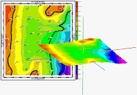
- 2D Grid Map
Check this box to display the output grid as a 2D map at this time.
Click this tab to set up the 2D map layers (bitmap, symbols, labels, line contours, color-filled contours, labeled cells, map border, etc.).
- 3D Grid Diagram
Check this box to display the output grid as a 3D surface at this time.
Click this tab to set up the 3D map layers (surface colors, images, reference cage, etc.).
! You can request both a 2D and 3D representation of the grid model.
This program requires that a non-RockWorks-format grid model exists, ready for import.
- Select the ModOps | Grid | Import menu option.
- Enter the requested menu settings, described above.
- Click the Process button to proceed.
The program will read the input grid file and translate it into a RockWorks grid file format. The requested diagram(s) will be displayed in a RockPlot2D tab and/or RockPlot3D tab in the Options window.
- You can adjust any of the settings in the Options window and then click the Process button again to regenerate the diagram(s).
- View / save / manipulate / export / print the diagram in the RockPlot2D or RockPlot3D window.
 Back to Grid Menu Summary

RockWare home page