RockWorks | Graphics | Images | Drape
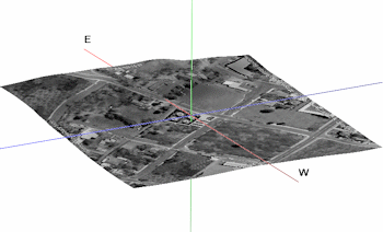
"Draped" bitmaps are images (maps, airphotos, etc.) that are warped over an existing grid (surface) model. This program requires input of an existing RockWorks grid model (.RwGrd file) and an existing raster image. Supported raster formats include: BMP, JPG, EMF and WMF, PCX, PNG, TGA, and TIFF.
! This program will stretch the image to fill the grid model boundaries.
! The image and the grid model must reside in the current project folder.
Menu Options
Step-by-Step Summary
- Drape Options: Click this tab to access the drape settings.
- Image Source
- Project Image: Click this option to drape the current Project Image.
- Other Image: Click this option to select a different raster image to drape.
- File Name: Browse for the name of the raster image you want to drape over the grid model. The supported file types are listed above.
- Drape Options
- Grid Name: Browse for the name of the surface model (.RwGrd file) that contains the elevations over which the image is to be draped. This can be a ground surface grid model, a formation grid model, etc.
- Layer Name: Type in a name for this layer; it will simply be used to label the image in RockPlot3D. For example, if the image represents a satellite image, you might name this layer "Satellite Image."
- Vertical Offset: Use this setting to offset the image above or below the grid model's surface. This can prevent interference between them if plotted together in RockPlot3D. The offset is entered in your project units; if your coordinates represent feet and you enter "5" then the draped image will be created at 5 feet above the grid model's surface. If set to 0, the image elevations will match the grid.
- Set Transparent Color: Insert a check in this box if you want to specify a specific color in the bitmap image to be displayed transparent. For example if the image has a white background and you would like that part to be see-through, you would select white.
If activated, click on the color box to choose the image color that is to be set to transparent.
- Other 3D Diagram Options
Use these checkboxes to append other layers to your 3D scene.
Click each tab to set up the 3D diagram layers (infrastructure, reference cage, etc.).
- Output Options
- Save Output File: Check this to assign a name for the scene in advance, rather than displaying it as Untitled.
- Automatic: Choose this option to have RockWorks assign the name automatically. It will use the name of the current program plus a numeric suffix, plus the ".Rw3D" file name extension.
- Manual: Choose this option to type in a name of your own for this file.
- Display Output: Check this option to have the resulting scene displayed in RockPlot3D once it is created.
- Select the Graphics | Images | Drape option from the RockWorks menu ribbon.
- Enter the requested menu settings, described above.
- Click the Process button to proceed.
The program will read the indicated raster image, assign it boundaries that equal the grid model boundaries, assign its pixels the elevations of the selected grid model (plus any defined offset), and display it in a RockPlot3D tab in the Options window.
- You can adjust any of the options along the left (such as offset or transparent color) and click the Process button to regenerate the 3D image.
- View / save / manipulate / print / export the image in the RockPlot3D window.
- Use RockPlot3D’s File | Save As to save the draped image view, then use File | Append to append an existing RockPlot3D view to this image.
 Back to Image Menu Summary

RockWare home page