
 Estimated time: 4 minutes.
In this lesson, you will be creating an image representing the Toluene T-Data measurements in multiple logs in the Samples project, selected along a multi-log cross section trace.
- Re-enable all of the boreholes in the project by clicking on the Edit | Enable All Boreholes menu option or toolbar button.

- Click on the Striplogs menu, and then click on 2D Striplog Section. (What's the difference between "profiles," "sections," and "projected sections"? Click here.)
- Establish the section options: These are found in the Main Options tab of the Striplog Section window.
- Vertical Exaggeration: This should be set to 1. In your own work, if your project area is large but your logs are shallow, this is a means of setting a vertical stretch for the section, before it's created, so that the border annotation is scaled well.
- Striplogs: Click this tab to confirm that none of the sub-options are checked. You'll set up the design of the striplogs in the next step.
- Log Spacing: Click here and be sure that this is set to Distance between Collar Locations.
 Hang on Datum: Uncheck this.
 Annotation: Check this. These options determine text and lines that will plot around the perimeter of the profile. Click on this tab to view the options; the factory defaults should be fine. See Restore Default Settings if you need more information about setting the factory defaults.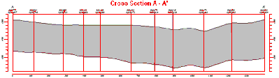
- or Surface Profile: If you completed the borehole map section of the tutorial (jump back), insert a check in the Surface Profile option. This is used to display a selected surface in the cross section plot. If you DID NOT complete that lesson, leave this un-checked.
- Click on this tab to access the Surface Profile options.
- Grid Model: Click on the browse button to the right of the prompt and select the .RwGrd file representing the ground surface, named Surface.RwGrd and click the Open button.
- Polyline Attributes: Click this tab to define the line's appearance.
- Line Style & Color: Click here to set the line style to red, medium thickness.
- Smoothing factor can be set to 1.
- Infrastructure: Unchecked.
- Other 2D Files: Unchecked.
- Peripherals: Unchecked.
- Border: Unchecked.
- Output Options: Use these settings to determine whether the diagram is to be displayed, saved in advance, and/or exported.
- Display: Checked.
- Save: Unchecked. We will save the diagram in the viewer.
- Export: Unchecked.
- Now let's move to the top of the window to adjust the log and section location settings.
- Spatial Filtering: Off
- Time Filter: This should still be on from the previous lesson, to filter the data for the Exact 2/14/17 sampling date.
- Strat Rules: Defaults will be fine here since we are not plotting any stratigraphy data.
- Click on the 2D Log Design tab where you will establish how the striplogs will look.
The program will display the 2D log designer window. This window has three main sections:
- The left pane is where you choose what type of data is to be displayed in the logs (the visible items).
- The upper-right pane is where you see a Preview of the active log items. You can drag the items to adjust their relative placement.
- The lower-right pane displays specific Options for the visible item that you click on.
a. Choose the items you want to see in the logs by inserting a check-mark in the following items in the left pane:
- Title: The drill hole name will plot above the logs.
- Depths: The logs will be labeled with depth tick marks and labels.
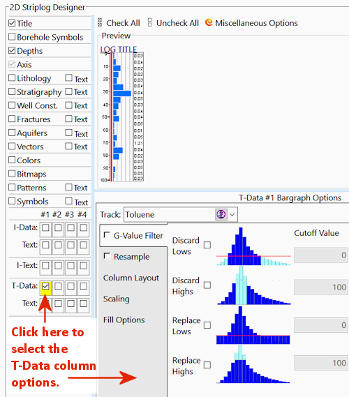
- I-Data: T-Data #1: The logs will contain a column illustrating T-Data values as a bargraph down the log. Note that you can activate up to 4 T-Data columns.
- Text: Insert a check in the Text option which sits below the T-Data #1 column - this will activate the plotting of text labels next to the bargraph. Below, you will select which information to display.
- None of the other options, including Text, should be checked in the left pane.
b. Adjust the arrangement of the visible log items: You should see four items in the upper Preview pane: title, depth bar, log axis, and T-Data.
- Practice clicking on an item, holding down the mouse button, and dragging it to the left or right in the preview.
- Try getting the items aligned in the following order:

! Note that the log axis is always activated, it acts as the anchor point for the log. The axis will be placed at the actual log location in the diagrams. The log title is always placed atop the axis.
c. Check the options for each visible item by clicking on the item's name in the listing; its options will be displayed in the Options pane.
- Next, pick the boreholes to display.
- Click on the Section Location tab.

- If you don't see the section trace pictured below, follow these steps; otherwise jump to the next item.
- Click on the Clear button at the top of the panel-picking window. The program remembers your cross section traces from session to session; this will clear any old traces from memory.
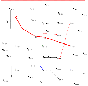
- Next, locate the hole titled DH-17 (toward the upper-left) and click on it. It will be marked with a red X.
- Locate hole DH-03 southeast of DH-17 and click on it. A line will be drawn between the holes.
- Locate hole DH-21 southeast of DH-03 and click on it.
! If you make a mistake, click the Undo button to undo the last pick or the Clear button to clear the slate for starting over.
- Click on DH-40, DH-41, and DH-07 continuing the cross section southeastward through the project area.
- You should see a trace like this:
- Location Map: Find this tab to the right of the 2D Log Design tab. Check this item. This will create a small map that shows the location of the section in the study area. Click on this tab to change:
- Output Options: Click this tab at the bottom of the window.
 Append Map to Diagram: Click in this radio button. Be sure the Size setting is set to Medium.
- Faulting: Click this tab to set up your Faulting Options in your striplog display and to modify fault options. (Read this for more details.)
- Click the Continue button at the bottom of the window.
RockWorks will create strip logs of each of the selected borings using the selected settings. The logs will be spaced proportionally to their distance from each other on the ground.
In addition, it will create a map that displays the location of the section slice within the study area.
The completed log section and location map will be displayed in a RockPlot2D tab, where 2-dimensional maps and other diagrams are presented.
- Zoom into the view: Since the labels appear fairly small, use the Zoom toolbar button
 to enlarge the logs in the middle of the section.
- Click on the Zoom button.
- Draw a zoom rectangle around the logs:

You can use the scroll bars to the right of and below the display to adjust the portion of the image that's in view.
! If you zoom in really far - "super-zoom" state - the scroll bars will no longer be displayed. You can use the Undo Last Zoom button  to step back outward in your zoom sequence.
- Edit a log label.
- Zoom in to the T-Data value label that is displayed on DH-40, which has the largest bargraph value.
- Click the RockPlot Edit button
 in the upper toolbar.
- Double-click on the label to be edited (or right-click on the label and choose Properties).
- Change the font color setting to red.
- Change the font Background: Click in the Opaque option and set the color to Yellow.
- Click the Apply button.
- You will see the label colors change in the display.
- Click Close to close this window.
- Click the Zoom Out button to return to full view.

- Experiment with the layers:
- If the Layers pane is not visible to the right of the display, click on the small, red "+" button in the upper-right corner of the plot pane.
- Remove/insert the check-mark from any of the layers, to see how they disappear from the display.
- You can drag the splitter between the Layers pane and the Data pane below it, to adjust the viewable space.
- Right-click on any layer in the list and choose Select Layer, and the layer will be shown as selected (with "handles") in the display.
- In your own work, you can right-click on any layer in the list and choose Delete to remove the layer from the diagram permanently.
- Save the cross section image for later overlay with another section diagram.
- With the section still displayed in the RockPlot window, choose File | Save, and type in the name: Toluene Log Section 2-14-17 and click Save. The program will save this image in its own
.Rw2D file format.
- You can close this RockPlot window by clicking in the close-window button (X).
See also: RockPlot2D tutorial
 Displaying Multiple Logs in a 2D Hole to Hole Section

RockWare home page

 Back to T-Data menu | Next (aquifer model)