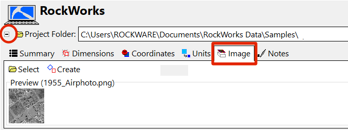
The Image tab in the RockWorks Project Settings is used to establish an image, typically an aerial photo, which can be used as a layer in many of the program's 2D maps.
You can assign location coordinates for the image using a World file, the current Project Dimensions, or by manually entering them. Image rectification tools are also offered.
If the Image tab is not visible, click the small button to the left of the project folder name. This toggles between "+" (expanding) and "-" (hiding) the Project Settings tabs.
- Select: If the image you wish to use is "ready" for use - meaning north-south oriented and not needing any clipping, click this button to select the image and assign location coordinates.
- File Name: Click here to browse for the file which contains the map image. BMP, JPG, EMF/WMF, PCX, PNG, TGA and TIF image formats are supported.
- Image Location Defined By...
- Project Dimensions: Check this option if the current output dimensions represent the border coordinates for the image you've selected.
- World File : Choose this option if there is an accompanying World File which defines the image extents.
- Automatic: Choose this option if the World file exists in the current project folder and has the same name as the image file defined above.
- Manual: Choose this option to browse for the World file to be used for georeferencing the selected image.
- Manually Specified: Choose this option if you want to type in the X and Y coordinates for each bitmap corner.
! RockWorks assumes that these coordinates match the coordinate system and units defined in the Project Dimensions.
- X Minimum: Enter the X (Easting) coordinate represented along the western edge of the image.
- X Maximum: Enter the X (Easting) coordinate represented along the eastern edge of the image.
- Y Minimum: Enter the Y (Northing) coordinate represented along the southern edge of the image.
- Y Maximum: Enter the Y (Northing) coordinate represented along the northern edge of the image.
- Create: If your project image needs any rotation or clipping, click this button to set up the rectification settings.
- Input: Browse for the file which contains the project image.
- Output: Click to the right to type in a name for the rectified image which will be created. This should be saved in the current project folder.
- Calibration Method:
- Project Corners: Click this button to use the current project dimensions for the image corners.
- 3-Points: Choose this option to define the real world coordinates for three known points on the image. They can be in any orientation, but remember the order in which you list them - you'll need to click on the points, interactively, in the same order in the next step of the process.
- Point 1: Click on the X and Y prompts to type in the X and Y coordinates for the first known point on the image.
- Point 2: Click on the X and Y prompts to type in the X and Y coordinates for the second known point on the image.
- Point 3: Click on the X and Y prompts to type in the X and Y coordinates for the third known point on the image.
- Clip Image: Insert a check here if you want to crop the image, and establish the crop dimensions below.
- Based on Project Dimensions: Choose this option to have the program crop the image using the current project dimensions.
- Based on Custom Dimensions: Choose this option to type in specific clipping coordinates. Expand this heading to enter these coordinates.
- Western Border (X-Min): Click here to type in the coordinate that is to become the left (western) edge of the image.
- Southern Border (Y-Min): Type in the coordinate that is to become the lower (southern) edge of the image.
- Eastern Border (X-Max): Enter the coordinate that is to become the right (eastern) edge of the image.
- Northern Border (Y-Max): Enter the coordinate that is to become the upper (northern) edge of the image.
- Create "World File": Check this box if you would like to create a "World File" that can be used in GIS (Geographic Information Systems) programs in order to correctly register (locate) an image relative to a mapping coordinate system. Use the settings to define how the World File name extension will be assigned. (The file name itself - the part before the "." - will be the same as the output image name.)
- Append "W": Choose this option if the file name extension of the World File should have the output file name extension plus the character "w". Example: If the rotated/clipped output image is named "Project 27.jpg", the World File will be named "Project 27.jpgw".
- Change Extension: Choose this if the file name extension of the World File should have 3-characters:
- The first character of the extension will equal the first character of the output file extension.
- The second character of the extension will be equal to the last character of the output file extension.
- The third character of the extension will be set to "W".
- Example: If the rotated/clipped output image is named "Project 27.jpg", the World File will be named "Project 27.jgw".
- Show in Google Earth: Check this box to have the Output Image displayed in Google Earth. This can be a great way to verify correct geo-referencing of the image.
- Set as Project Image: Check this to assign this image as the project image, which can be quickly added as a layer in your graphic output.
- Show Report Describing Rectification Accuracy: Check this box to see a summary of the image coordinates. These will represent the clip edges, if you have clipping activated (above) or simply the rectified image if no clipping was requested.
- Continue: Click this button to perform the rectification.
- Global settings for information about settings which apply to all projects in RockWorks.
 Back to Project Settings

RockWare home page