RockWorks | Graphics | Image | Image Cube
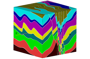
Use this program to display raster images on one or more cubes for display in RockPlot3D. Supported bitmap formats include: BMP, JPG, EMF and WMF, PCX, PNG, TGA, and TIFF.
Menu Options
Step-by-Step Summary
- Data Columns: Use these prompts to specify where the required data is listed in the current datasheet.
- Title: Choose the column that contains the title, if any, for each cube. This will be used as the label for the cube in RockPlot3D.
- X Center, Y Center, Z center: Choose the three columns that contain the location coordinates for the center of the cube.
These can be defined in your project coordinates or other coordinate system. See Defining your Datasheet Coordinates for more information.
- Width, Depth, Height: If you have requested Variable cube dimensions (see below), you need to specify here the columns in the datasheet that list these dimensions. If you've specified a fixed size for the cube(s), these settings will be ignored.
- Base Pic, Top Pic, West Pic, East Pic, South Pic, North Pic: Choose the columns that list the file names of the images that will be displayed on the specified faces of the cube. Be sure the images are in the current project folder. Supported file types are listed above.
- Options
- Cube Dimensions
- Fixed: Click here if all cubes are to have the same dimensions. Enter the width, depth, and height. These units can be virtually anything, but if they are to overlay any other real-world images they must correspond to that unit system.
- Variable: Click here if you've listed dimensions in the datasheet. Be sure the Width, Depth, and Height columns are correctly defined under the Data Columns tab.
- Image Opacity: Select from the following:
- Transparent: Choose this option if you want to specify a specific color in the bitmap images to be displayed transparent. For example if the images have a white background and you would like that part to be see-through, you would select white.
If activated, expand this heading to click on the color box to choose the image color that is to be set to transparent.
- Opaque: Choose this option to display the images as opaque. Note that you can also adjust overall transparency of the faces in RockPlot3D itself.
- Other 3D Diagram Options
Use these checkboxes to append other layers to your 3D scene.
Click each tab to set up the 3D diagram layers (reference cage, etc.).
- Output Options
- Save Output File: Check this to assign a name for the 3D scene in advance, rather than displaying it as Untitled.
- Automatic: Choose this option to have RockWorks assign the name automatically. It will use the name of the current program plus a numeric suffix, plus the ".Rw3D" file name extension.
- Manual: Choose this option to type in a name of your own for this RockPlot3D file.
- Display Output: Check this option to have the resulting scene displayed in RockPlot3D once it is created.
- Access the RockWorks Datasheet program tab.
- Open a data file that contains a listing of XYZ locations and picture names, with optional dimensions and titles.
- Select the Graphics | Images | Image Cubes menu option.
- Enter the requested menu settings, described above.
- Click the Process button to proceed.
The program will read the listed images and build 3D cubes at the specified XYZ locations, using the specified cube dimensions. If requested they will be displayed in a RockPlot3D tab in the Options window.
- You can adjust any of the diagram options in the pane to the left and then click the Process button again to regenerate the 3D image.
- View / manipulate the image in RockPlot3D.
 Back to Image Menu Summary

RockWare home page