Step 1: Enter your known data.
In order to use the Pick Lithology Intervals tool for your project, you need to have some known data from which you will indentify the lithology materials. Typically this would be downhole geophysical (elog) measurements or raster logs. See Entering the Borehole Data for details.
Step 2: Build a "Practice" Hole to Hole Section (Striplogs menu)
Once your known data is entered into the Borehole Manager tabs, you should next display the data as logs in one or more hole to hole cross sections. While this isn’t an essential step, displaying your known data can be very helpful in:
- Determining if your data is good (e.g. if the elog data is adequate to pick lithotypes),
- Establishing the appropriate logs settings for good visualization of the data (required for good results with the Pick Intervals tool), and
- Determining the material types that you will be picking (next step).
This example shows an elog section created using the Striplogs | 2D Striplog Section program.
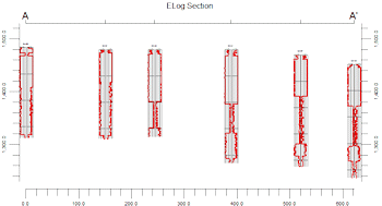
Once you have your hole to hole section(s) displayed in a RockPlot2D window, take a good look at the logs, pick up a pencil and write down the names of the lithology materials that you will be picking.
Step 3: Define Lithology Types
With a good idea of the look of the existing downhole geophysical data, you need to define the Lithology "Types" or materials that are represented in your project. When you run the Pick Lithology Intervals tool (next step) the program will read the current Lithology Types Table and display those material types as the ones that will be picked.
See Lithology Types Tables for details.
Step 4: Set Up the Lithology Picker Display
- With your preliminary work done, select the Striplogs | Lithology Picker menu option.
- Lithology Picker Options: Enter the Lithology Picker Settings along the left side of the Options window.
- Set up the log display: Click on the 2D Log Design button along the top, to define which available log items are to be displayed in the logs. For each item you wish to include, insert a check in its check-box, and then establish its particular settings in the pane to the right. Please refer to the Log Item Summary for more information.
If you completed Step 2, you can use the same settings as you used for your hole to hole section.
! Be sure the appropriate log items (Images? Curves?) are turned on for your lithology analysis.
Step 5: Select the Wells to be Displayed
- Click on the Section Location button along the top of the window, to select which wells are to be displayed in the lithology picker.
- Pick the wells:
- If you wish to discard any existing selections, click the Clear button. Otherwise, any new wells selected will be added to the existing list.
- To include a particular well in the lithology picking diagram, simply position the pointer on it, and left-click the mouse. "Selected" wells will be shown as connected along a pink line representing the cross section trace.
-
- Click on as many wells as you wish to include in the well picking window. The well logs will be displayed in the diagram from left to right in the order you select them, first to last. Be cautioned, however, that if your project contains numerous wells, it’s best to do this in several passes. Otherwise, there may be too many logs for good viewing.
- Refer to Drawing Cross-Sections for additional details and options.
- Click on the Continue button to display the selected wells in the lithology picker window.

RockWare home page