Faults | Import | Polyline -> Vertical 3D Fault
This program creates a vertical 3D fault based on a list of XY points in the datasheet, and minimum and maximum elevations. The fault is stored in the project Fault table. The program expects negative values for the Dip Angle (Inclination).
See also
Polyline -> 2D Fault to create a 2D fault from a polyline.
! The number of faults you can maintain in your project is determined by the feature level of the software:
- Basic: 3 Faults
- Standard: 10 Faults
- Advanced: Unlimited Faults
Menu Options
Step-by-Step Summary
- Input Columns: Use these prompts to tell RockWorks which columns in the datasheet contain the input data.
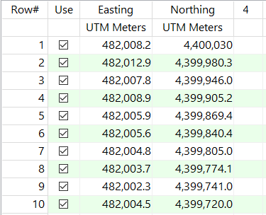
Click on an existing name to select a different name from the drop-down list. See a sample data layout below.
- X (Easting): Column that contains the X or Easting coordinates for the fault polyline vertices.
These can be Eastings in meters or feet, decimal longitudes, etc. See Defining your Datasheet Coordinates for more information.
- Y (Northing): Column that contains the Y or Northing coordinates for the vertices.
- Upper Elevation (Z max): Choose the input type for the top of the fault. Choose Constant, Variable, or Grid. If you want to use a grid it must exist in the project already.
- Lower Elevation (Z min): Choose the input type for the bottom of the fault. Choose Constant, Variable, or Grid. If you want to use a grid it must exist in the project already.
- Inclination (Dip): Choose how to show the dip of your fault plane; Vertical, Constant, Variable, or Conical.
- Attributes: Use these settings to establish general fault and display settings. These will be stored with the fault in the database and can be accessed/edited using the Edit Fault button in the Faults tab.
-
- Fault Name: Enter the name to assign to the fault, to distinguish it from other faults. This is displayed in the Name column in the Faults table, and can be displayed as labels on the fault polylines.
- G-Value: Assign a G-Value to the fault. This is assigned to model nodes that intersect the fault triangles.
- Comment: Use this optional field to list any descriptive comments for the fault, for your reference only.
- Line Style: Choose a line color and style with which to represent the fault in 2D maps and sections, and as a polyline in 3D.
- Fill Color: Assign a Fill Color for the fault meshes when displayed in 3D.
- Add Symbols: Check this item to have the option of including symbols along the fault polylines in 2D maps.
- Type of Symbol: Choose a symbol type from the drop-down list. If you choose a Custom type, click to the right to select the custom symbol design.
- Symbol Line Thickness: Click the up/down arrows to assign a thickness for the lines which will make up the fault symbols. "1" will generate thin lines, "3" relatively thick lines.
- Access the RockWorks Datasheet program tab.
- Create a new datasheet and enter/import your XY polyline coordinates into the datasheet. The minimum number of points required to create the fault is 2.
Or, open one of the sample files and replace that data with your own.
! Click the Example button at the top of the window to load a sample file that is installed with the program.
This example illustrates the sample file "\Documents\RockWorks Data\Samples\Fault_Import_Polyline.rwDat")
- Access the Faults program tab.
- Select the Faults | Import | Polyline -> Vertical 3D Fault menu option.
- Enter the requested menu settings, described above.
- Click the Continue button to proceed.
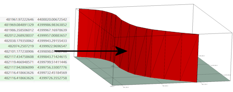
RockWorks will read the polyline vertex coordinates and elevations for the line and create a series of connected triangular panels representing the vertical panel. The triangle mesh will be stored in the Faults table in the project database.
- You can now use this fault, along with other enabled faults in the Fault table, when creating a surface model or solid model and applying faulting.
 Back to Faults Program Tab

RockWare home page