Faults | Import | Dips -> 3D Fault
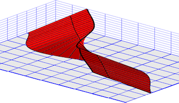
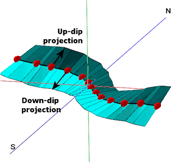
This program reads from the RockWork Datasheet a list of dip data (e.g. points along a fault, contact, bedding plane which include XYZ coordinates, dip direction, and dip angle), fits a smooth curve to the points in the order in which they are listed, and a triangle mesh is then projected up-dip and/or down-dip from the curve. The fault is stored in the project Fault table.
! The number of faults you can maintain in your project is determined by the feature level of the software:
- Basic: 3 Faults
- Standard: 3 Faults
- Advanced: Unlimited Faults
Menu Options
Step-by-Step Summary
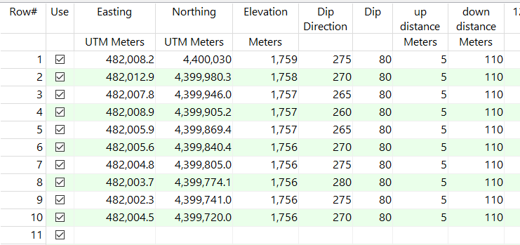
- Input Columns: Use these prompts to tell RockWorks which columns in the datasheet contain the input data.
Click on an existing name to select a different name from the drop-down list. See a sample data layout below.
- X: Column that contains the X or Easting coordinates for the fault polyline vertices.
These can be Eastings in meters or feet, decimal longitudes, etc. See Defining your Datasheet Coordinates for more information.
- Y: Column that contains the Y or Northing coordinates for the vertices.
- Z: Column that contains the elevations where the measurements were taken. Be sure you've defined the elevation units in the column heading.
- Dip Direction: Choose the column that lists the Dip Direction or Strike Direction (defined below), in degrees. (examples: North = 0, East = 90, South = 180, and West = 270.)
- Dip Angle: Choose the column that lists the dip angle. Note: Horizontal is considered to be zero, and dipping straight down is entered as +90.
- Downslope Distance: Choose either fixed or defined in the datasheet.
- Uniform: Choose this to apply a uniform down-dip distance for all of the input points. Click in the prompt to enter the the distance in your project units. If you do not wish to project down-dip, enter 0 here.
- Defined by a Column: Choose this option if you have the down-dip distance defined for each point in the datasheet. Click the down-arrow to select the name of the column where these measurements are recorded. Be sure you've defined the elevation units in the column heading.
- Upslope Distance: Choose either fixed or defined in the datasheet.
- Uniform: Choose this to apply a uniform up-dip distance for all of the input points. Click in the prompt to enter the the distance in your project units. If you do not wish to project up-dip, enter 0.
- Defined by a Column: Choose this option if you have the up-dip distance defined for each point in the datasheet. Click the down-arrow to select the name of the column where these measurements are recorded. Be sure you've defined the elevation units in the column heading.
-
- Directionality: Choose how the data listed in the datasheet are recorded.
- Magnetic Declination Correction: Use this setting to correct for magnetic declination, in degrees.
- Azimuths (Directions) Represent:
- Inclination (Dip) Direction: Using this convention, planar data are entered with dip direction and dip angle.
- Strike Direction: Using this right hand rule convention, planar data are entered as strike bearing and dip angle, with the dip direction being 90 degrees clockwise from the strike azimuth bearing.
- Attributes: Use these settings to establish general fault and display settings. These will be stored with the fault in the database and can be accessed/edited using the Edit Fault button in the Faults tab.
- Fault Name: Enter the name to assign to the fault, to distinguish it from other faults. This is displayed in the Name column in the Faults table, and can be displayed as labels on the fault polylines.
- G-Value: Assign a G-Value to the fault. This is assigned to model nodes that intersect the fault triangles.
- Comment: Use this optional field to list any descriptive comments for the fault, for your reference only.
- Line Style: Choose a line color and style with which to represent the fault in 2D maps and sections, and as a polyline in 3D.
- Fill Color: Assign a Fill Color for the fault meshes when displayed in 3D.
- Add Symbols: Check this item to have the option of including symbols along the fault polylines in 2D maps.
- Type of Symbol: Choose a symbol type from the drop-down list. If you choose a Custom type, click to the right to select the custom symbol design.
- Symbol Line Thickness: Click the up/down arrows to assign a thickness for the lines which will make up the fault symbols. "1" will generate thin lines, "3" relatively thick lines.
- Access the RockWorks Datasheet program tab.
- Create a new datasheet and enter/import your dip-direction/dip-angle data into the datasheet. The minimum number of points required to create the fault is 2.
Or, open one of the sample files and replace that data with your own.
! Click the Example button at the top of the window to load a sample file that is installed with the program.
This example illustrates the sample file "\Documents\RockWorks Data\Samples\Fault_Import_Dips.rwDat")
- Access the Faults program tab.
- Select the Faults | Import | Dips -> 3D Fault menu option.
- Enter the requested menu settings, described above.
- Click the Continue button to proceed.
RockWorks will read the indicated XYZ location coordinates and create a series of connected triangular panels that are projected up-dip and/or down-dip from the control points. The triangle mesh will be stored in the Faults table in the project database.
- You can now use this fault, along with other enabled faults in the Fault table, when creating a surface model or solid model and applying faulting. You can display this fault, along with other enabled faults, as a 2D or 3D diagram using the programs in the Faults tab Display menu, or using the Faults layer in most RockWorks 2D and 3D diagram menus.
 Back to Faults Program Tab

RockWare home page