- First, follow the steps for opening the Stratigraphy Types Table.
- To delete a row in the Stratigraphy Types Table, click in the row, right-click, choose Rows, and then Delete. (Alternatively, you can type Ctrl+Del.)
! If there are any borehole data records that reference this stratigraphy type you will see a warning as such. You can choose to (1) delete all of those borehole data entries, (2) change the entries to another formation name, or (3) cancel the deletion operation by clicking the Cancel button.
- To insert a row in the Stratigraphy Types Table:
- At the end of the listing, click in the last Formation cell and press the down-arrow key. Or...
- In the middle of the listing, click in the cell above which you wish to add the new row, right-click and choose Rows, and choose Insert. The program will insert a new row into the table, with an undefined formation type.
- Then, click in the appropriate cell to enter the required information:
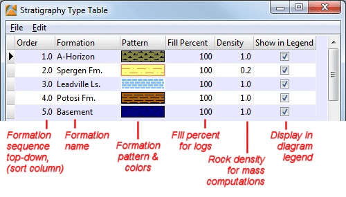
- Order: This field is used to define the order of the units from the ground downward. Unlike Lithology Types, which can be listed in any order, Stratigraphy Types should be listed in order, with upper formations first and lower formations last. The formation with the lowest Order number (listed in the Table) needs to be the uppermost formation in the study area, and so on. The Stratigraphy order is important because many modeling tools rely on the order to give priority to certain formations. The Order number is also assigned to formations should you create a stratigraphy solid model.
! Note: If your stratigraphic sequence is poorly defined (as is common with imported datasets), and you cannot assign a specific order to the units, then you can assign these arbitrarily and rely on the Stratigraphy Rules for log and section plotting.
- Type in the sequential order for each formation, starting with "1" for the uppermost formation and numbering sequentially downward. If the names are not currently sorted in the right order, don't worry - the next time you view this table, they'll be sorted in the proper sequential order.
- Or, select the Edit | Renumber Stratigraphy Order option to reset the numbers in the Order column to sequential order, starting with 1 at the top, based on the current display order. This is handy to use if the display order is consistent with the actual formation order.
- Formation: This column lists the formation names. Formation names are linked to the borehole Stratigraphy data. By default, the listing will be sorted based on the number in the Order column. You can sort based on formation name by clicking on the Formation column heading.
- To add a formation name to the end of the list, click in the last Name cell and press the down-arrow key. A new, undefined stratigraphy type will be listed. Type in the name for the new formation to be added. Formation names can be single or multiple words, up to 60 characters in total length. Or...
- To add a formation name to the top or middle of the list, click on the row above which you want to insert the formation. Right-click and choose Rows | Insert. A new, undefined stratigraphy type will be listed. Type in the name for the formation to be added.
- Pattern:
- Select a pattern for a formation by double-clicking in the Pattern cell of that row. The program will display the Select Pattern window.
- From the displayed pattern library, click on the desired pattern design.
- Set the foreground and background colors using the color boxes at the top of the window. In strip logs and profiles, the pattern design will be drawn in the declared foreground color, on top of the declared background color.
- ! The background color will be used to represent the formation in 3D surface maps, and fence and block diagrams which do not include the pattern designs.
- Set the pattern's density by clicking the up or down Density arrows. The higher the number, the larger the repeating pattern block (and the lower the pattern density).
- The Preview box will show you the current pattern design, colors, and density.
- Set the pattern's line or dot width by clicking the up or down Line Width arrows. This will be updated in the Preview display. This capability is especially useful for enhancing single-dot patterns (e.g. sandstone) that may not be otherwise visible on higher resolution devices (e.g. printers).
- Accept the current settings for the current formation by clicking OK at the bottom of the Select Pattern window.
- Fill Percent: This setting affects stratigraphic pattern fill in strip logs only.
- Click in the Percent column for the formation you are modifying.
- Type in a number between 0 and 100, to note how much of the stratigraphy column in strip logs will be filled with pattern and color.
- The following examples show the effect of different percentage fills on the resulting 3D strip log.
-
- Density: This setting is used only when formation mass is being computed for stratigraphic solid models.
- Click in the Density column for the formation you are modifying.
- Type in a density multiplier for the cubic units in which you are working.
- For example, if your well locations and depths are expressed in feet, then your volume units will be cubic feet. This density multiplier should be entered in pounds (or tons) per cubic foot.
- If your well locations and depths are entered in meters, then your volume units will be cubic meters, and the density multiplier should be entered in kilograms (or grams) per cubic meter.
- See also Measuring your rock density
- If you don't know what to enter, just leave the Density value at 1.
- Show in Legend: This setting allows you to specify:
- Which of the formation names are to be displayed in the diagram legends. This can be helpful if your project has a number of formation names, but images generated for one portion of the project only reference a few of the formations. By removing the checks from the other names, only the selected formations would be displayed in the diagram legends.
- Which of the formations are to be included during stratgraphic modeling. This "Stratigraphy Types to Be Included" option (in the Stratigraphy menu, Model, Section, Profile, Projected Section, Fence, Surface Map, and Plan Map programs) allows you to selectively include only the checked formations during modeling.
- Insert a check in each formation's check-box if it is to be represented in diagram legends and/or in stratigraphic models and associated diagrams.
- When your editing is complete, click the OK button at the bottom of the table editor to close the window. Note that changes you make to the Stratigraphy Types Table are posted on the fly. You do not need to manually save the changes you make.
 Back to Stratigraphy Types Table Overview

RockWare home page