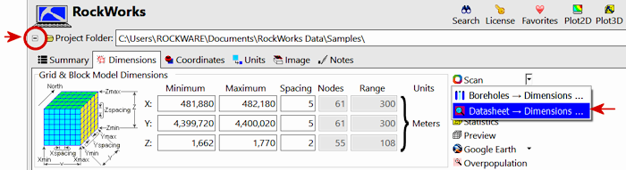
Use the Scan Datasheet button in the Project Settings | Dimensions pane to quickly establish your project's output dimensions, or to update existing dimensions, based on data stored in the Utilities Datasheet.
To access this pane, click on the small button to the left of the project folder name. This toggles between "+" (expanding) and "-" (hiding) the Project Settings tabs.
- Data Columns: The prompts along the left side of the window tell RockWorks which columns in the input datasheet contain the required data.
Click on an existing name to select a different name from the drop-down list.
- X-Column: Column that contains the X-Coordinates (east-west) upon which the output dimensions are to be based.
- Y-Column: Column that contains the Y-Coordinates (north-south) upon which the output dimensions are to be based.
- Z-Column: Column that contains the elevation coordinates upon which the output dimensions are to be based (if you choose to scan for XYZ dimensions, below).
- Options
- Items to be scanned:
- XY Data: Choose this option if the program is to scan the data in the specified X-Column and Y-Column to determine the west<->east and south <-> north extents of your project. (Choose this if you are not doing any solid modeling.)
- XYZ Data: Choose this option if the program is to scan the data in the specified X-Column, Y-Colum, and Z-Column to determine the west<->east, south <-> north, and min-max elevations for the output dimensions. (Choose this if you are doing any solid modeling.)
- XY Node Spacing Based on: Use these settings to define how the horizontal resolution of your models is to be determined.
- Point Distance: Click in this button if you want the scanned node spacing to be based on the average minimum distance between control points.
- Multiplied by: In the prompt, type in the multiplier to be used. If set to "1", then your models will be generated with an average of 1 node between data points. If set to "0.5", your models will have an average of 2 nodes between points. If set to "0.1", there will be about 10 nodes between points.
- If your node density is too high, increase the multiplier value and re-scan using the buttons at the top of the window.
- ! If you have a lot of rows to scan, the process of computing the average point-to-point distance can take a while You might consider using the Fixed Nodes option, below.
- Adjust to 50 x 50 node minimum: Use this checkbox (on by default) to be sure that the density of the nodes is at least 50 nodes along the X and Y axes.
- Specific Distance: Select this option if you want to define the actual distance between nodes along the X and Y axes.
- XY Node Spacing (In Output Units): To the right, type in the actual spacing between your grid and solid model nodes, along the X and Y axes. For example, if you know that you want your models to be created with 25-foot spacing, you would enter "25" into this prompt (assuming your output units are in feet).
- Fixed Nodes: If you choose this option, then the scanned node spacing will generate the requested number of nodes. For example, if set to "50", the program will set the node spacing such that approximately 50 nodes are created. (You may not get the exact amount if you've activated the Tidy-up settings below.)
- X Nodes: Type in the number of nodes you want along the X axis.
- Y Nodes: Type in the number of nodes you want along the Y Axis. The node count (and spacing, for that matter) can be different along the X and Y axes.
- Z Node Spacing Based on: Use these settings to define how the vertical resolution of your models is to be determined.
- Vertical Distance: Select this option if you want to define the actual distance between nodes along the Z axis.
- Vertical Node Spacing (in Output Units): Click to the right to type in the actual spacing between your solid model nodes, along the Z axis. For example, if you know that you want your models to be created with nodes at 10-foot spacing, you would enter "10" here (assuming your output units are in feet).
- Fixed Number of Nodes: This is a fixed node setting - type in the number of nodes to generate for the vertical axis of your solid models. If set to "25" the program will set the node spacing such approximately 25 nodes are created.
- Adjust Dimensions to Tidy Increments: If checked, the program will perform the following operations when scanning the datasheet:
- Extraneous decimal places will be removed from the Min/Max/Spacing data.
- The node spacing will be rounded to reasonable numbers (e.g. 79.5 might become 100.0 depending upon the range of the data).
- The extents of the project will be increased such that they are multiples of the node spacing while simultaneously ensuring that all points are enclosed by the new boundaries.
- Margins: If set to 0.0 (default) the scanned boundaries will comply with the point boundaries, with only slight adjustments for the "tidy" setting, above. If you prefer that map boundaries and models be created slightly outside the data extents, you can set the horizontal and vertical margins to a percent of that dimension. For example, if they are set to "5", then the scanned dimensions will be pushed outside the data by an extra 5%.
Back to Project Dimensions
RockWare home page