The input for the Infrastructure programs consists of a text file that contains a series of simple commands representing objects and object parameters.
"Objects" define what is to be plotted while "parameters" define how subsequent objects will be plotted.
The object and parameter commands must end with a colon (:) character.
Spaces or tabs may be used to separate fields within the Infrastructure file.
The objects and parameters within an Infrastructure file are processed in a top-to-bottom fashion. This means that a parameter change will effect items below it. For example, if the COLOR command is used, all subsequent objects will use the last-specified COLOR setting.
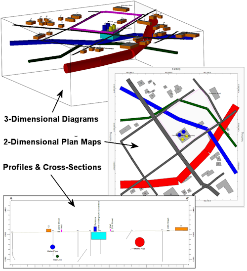
Objects within Infrastructure files may be plotted as a layer in your 3D diagrams (fences, solids), in your 2D maps, and within profiles and sections.
Infrastructure replaces "Surface Objects" from earlier versions of RockWorks. We have removed/replaced the following Surface Objects items:
CONE: Removed.
CYLINDER: Replaced by VTANK.
LABEL: Removed.
OBLATE: Removed.
TUBE: Replaced by PIPE.
STRUCTURE: Replaced by SUB_BUILDING.
Infrastructure Parameter Summary - click on a link to jump to the parameter
ELEVATION
SURFACE
COLOR
HEIGHT
RADIUS
ROAD_WIDTH
ROAD_OFFSET
TEXT_2D_SIZE
TEXT_3D_SIZE
Infrastructure Object Summary - click on a link to jump to the object
BUILDING
PIPE
ROAD
SUB_BUILDING
VTANK
WALL
Special Commands - click on a link to jump to the command
Infrastructure Parameters
ELEVATION (Parameter): Defines the elevation at the base of all subsequent surface objects.
Should be the first item within an Infrastructure file.
If the SURFACE command is absent, the ELEVATION parameter will define the base elevation for all surface objects.
If the SURFACE is defined, the ELEVATION will define the base elevation for any surface objects (or portions thereof) that extend beyond the lateral range of the SURFACE.
The ELEVATION has no effect when displaying an Infrastructure file as a two-dimensional map.
If unspecified, the ELEVATION will be set to zero.
Example:
ELEVATION: 1760
SURFACE (Parameter): This optional command is used to define a grid model that is used to determine the base elevation for all subsequent surface objects.
The SURFACE parameter should be the second item within an Infrastructure file.
The specified SURFACE must be stored within the current Project Folder.
The SURFACE has no effect when displaying an Infrastructure file as a two-dimensional map.
Example:
SURFACE: Ground_Surface.RwGrd
COLOR (Parameter): Defines the color of all subsequent objects, except for the building roof color, which is defined by the ROOF_COLOR parameter.
The actual color may be specified by it's name (e.g. "Red") or the Windows color number.
Example:
COLOR: Red
HEIGHT (Parameter): Defines the height of subsequent BUILDING, SUB_BUILDING, VTANK, and WALL objects.
Example:
HEIGHT: 20
The HEIGHT parameter has no effect when plotting Infrastructure data within a plan-view map.
RADIUS (Parameter): Defines the radius of subsequent PIPE and VTANK objects.
Example:
RADIUS: 10
Example:
ROAD_WIDTH: 20
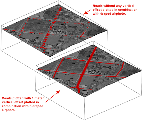
ROAD_OFFSET (Parameter); Defines an vertical offset between the specified road vertices and the actual road elevation.
The ROAD_OFFSET parameter is designed to elevate the road slightly to avoid "visual interference" effects when plotting an Infrastructure file in combination with a draped image.
Example:
ROAD_OFFSET: 5
The ROAD_OFFSET parameter is only recognized by the 3D Infrastructure compiler.
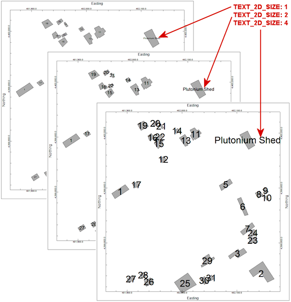
TEXT_2D_SIZE (Parameter): Defines the size of textual annotation within plan-view maps, profiles, and sections.
The size of 2D text is defined as a percentage of the project size (i.e. the distance between the southwest and northeast corners of the project area).
Example:
TEXT_2D_SIZE: 1.0
If the TEXT_2D_SIZE command is absent, a size of 1% will be used.
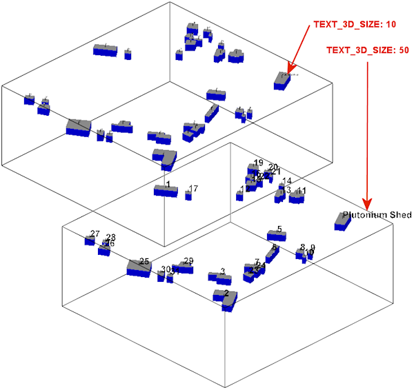
TEXT_3D_SIZE (Parameter); Defines the size of the text within three-dimensional depictions of the Infrastructure file.
Unlike the TEXT_2D_SIZE, the TEXT_3D_Size is an integer that is defined in terms of "points".
Example:
TEXT_3D_SIZE: 10
If the TEXT_3D_SIZE command is absent, a size of 10-points will be used.
Infrastructure Objects
BUILDING (Object): This command is used to plot buildings that sit on the ground surface (as defined by the DEFAULT_ELEVATION and/or the SURFACE MODEL).
In the case of the SURFACE_MODEL, the base of the building will be set to the lowest grid value for any of the BUILDING vertices.
The BUILDING command is followed, on the same line, by an name/title of the BUILDING.
This title will appear with the RockPlot-2D and RockPlot-3D data lists so that can be turned on and off after the diagram has been rendered.
- This title is also used to annotate the BUILDING if the Plot Titles menu option is enabled.
The vertices for the building are listed in XY pairs below the BUILDING command line and are terminated by an END flag.
Example:
BUILDING: Chemical Storage Warehouse
481877.8 4399880.6
481872.1 4399890.2
481896.6 4399906.3
481903.6 4399897.4
END:
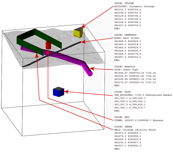
PIPE (Object): This command is used to plot underground pipes, tunnels, subways, and buried tanks.
The PIPE command is followed, on the same line, by the object title (e.g. "Gas Pipe"), followed, on separate lines by the XYZ coordinates for points along the pipeline, and terminated by the "END:" flag.
Example:
PIPE: Sewer Pipe
481949.87 4399753.18 1725.32
482024.87 4399761.08 1730.92
482099.88 4399837.34 1735.90
482174.87 4399955.51 1741.23
END:The color and radius of the PIPE are defined by the COLOR and RADIUS parameters respectively.
ROAD (Object): This command is used to plot horizontal panels that connect a list of vertices to create the appearance of a road.
The ROAD command is followed, on the same line, by the object title (e.g. "Broadway Boulevard"), followed, on separate lines by the XY coordinates for points along road, and terminated by the "END:" flag.
Example:
ROAD: East Street
481894.0 4400024.1
481900.5 4400014.1
481963.0 4399924.3
482026.3 4399833.4
482066.3 4399779.6
482087.4 4399751.2
END:The color of the ROAD is defined by the COLOR parameter.
A special parameter titled "ROAD_OFFSET" is used to uniformly elevate the ROAD objects.by a specified distance. This offset is used to eliminate "visual interference" effects when plotting an Infrastructure file in combination with a draped image (see example for ROAD_OFFSET above).
SUB_BUILDING (Object): This command is used to plot a building in which the base of the building is below the ground surface.
The SUB-BUILDING command is followed, on the same line, by the elevation at the base of the building, and the title for the building. The remaining lines define the XY coordinates the building vertices, terminated by the END: flag.
Example:
SUB_BUILDING: 1700.0 Underground Bunker
481,925.1 4,399,858.2
481,908.0 4,399,882.1
481,931.3 4,399,899.1
481,948.1 4,399,874.7
END:The color, height, and roof color for a SUB_BUILDING are determined by the COLOR, HEIGHT, and ROOF_COLOR parameters respectively.
VTANK (Object): This command is used to plot cylindrical tanks that sit on the ground surface (as defined by the DEFAULT_ELEVATION and/or the SURFACE_MODEL).
The VTANK command is followed, on the same line, by the XY coordinates at the tank midpoints followed by the name/title for the VTANK object.
Example:
VTANK: 482036.2 4399868.5 PCB Storage Tank
The color, radius, and height of a VTANK are determined by the COLOR, RADIUS, and HEIGHT parameters respectively.
WALL (Object): This command is used to plot vertical panels that connect a list of vertices to create the appearance of a wall or fence.
The WALL command is followed by the wall title. Subsequent lines contains the XY coordinates for the wall vertices and terminated by the END: flag.
Example:
WALL: Storage Facility Fence
482027.1 4399841.4
481972.6 4399924.7
482079.3 4399999.1
482089.3 4399993.8
482130.3 4399917.0
482027.1 4399841.4
END:The color and height of a WALL are determined by the COLOR and HEIGHT parameters.
Special Commands
GROUP_START (Special Command): The GROUP_START and GROUP_END commands are used to organize items into groups that can be enabled (made visible) and disabled (make invisible) within the RockPlot2D and RockPlot3D data "trees".
The GROUP_START command is followed, on the same line, by the name of the group.
Example:
GROUP_START: Storage Tanks
VTANK: 482027.9 4399879.7 Benzene
VTANK: 482038.9 4399887.8 Mercury
VTANK: 482036.2 4399868.5 PCB's
VTANK: 482046.9 4399876.3 Thorium
GROUP_END: Storage Tanks
GROUP_END (Special Command): See above.
HALT (Special Command): This is an optional command that will terminate the processing of the Infrastructure file. It exists so that information may be added to the end of the file without corrupting the command set.
&npsp;
![]()