RockWorks | Borehole Manager | Striplogs | 2-Dimensional | Profile
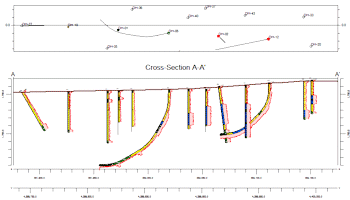
Use this tool to create a projected 2-dimensional display of strip logs of multiple boreholes, displaying observed data entered into the borehole data tables. The logs can include any combination of the available log items. The borings can be displayed as vertical, inclined, or deviated. The completed projected cross section will be displayed in the RockPlot2D window.
See also:
Menu Options
Step-by-Step Summary
Menu Options
- Clip (Truncate Logs): Insert a check in this box if you want to display a subset of the log data in the profile.
- Expand this heading to define the elevation range to be displayed. (More.)
! Log clipping parameters are defined using elevations, not depths.
- Include Stripmap: Insert a check here to include a stripmap above or below the profile diagram, which depicts the position of the logs within the search "swath" relative to the profile.
- Expand this heading to establish the Stripmap location and appearance options. (More.)
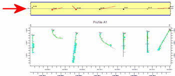
- Show Collar Distances: Insert a check in this box to display at the top of the profile a series of labels that represents each borehole's distance to the profile line.
- Expand this heading to set up the profile distance optins. (More.)
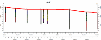
- Plot Surface Profile: Insert a check here to include a line on the profile that represents a user-selected grid model, typically the ground surface. Expand this heading to access the profile options.
- Surface Profile Options: Click the Options button to select the grid model to be represented, and to establish the profile settings. (More.)
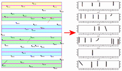
- Create Additional Parallel Profiles: Check this box if you want multiple profile lines to be drawn automatically, offset from the profile that you define.
- Expand this heading to define the direction and spacing of the automatic profile lines, the maximum distance, and diagram labeling options. (More.)
- Show Fault(s): Check this box if you want to display vertical lines in the output diagram where the profile slice intersects the fault(s) defined in a project Faults Table.
- Expand this heading to set up the fault lines. (More.)
- Show Infrastructure: Check this box to display buildings, pipes, or other infrastructure with your profile. Click the Options button to define the infrastructure file and plot settings. (More.)
-
- Perimeter Annotation Options: Click this Options button to establish title, border, and vertical exaggeration settings for the profile. (More.)
-
- Create Location Map: Insert a check here to have the program create, along with the profile, a reference map that shows the profile cut's location. It can be embedded in or created separately from the profile.
- Expand this heading to establish the map options. (More.)
- Legends:
- Aquifer Legend: If you're including a water level column in your logs, you can insert a check here to include a legend that lists all of the aquifer names and their colors and patterns, as listed in the project's Aquifer Types Table. Expand this item to set the legend size, appearance, and other options. (More.)
- Lithology Legend: If you're including a lithology column in your logs, you can insert a check here to include a legend that lists all of the lithology keywords and their colors and patterns, as listed in the project's Lithology Types Table. Expand this item to set the legend size, appearance, and other options. (More.)
- Stratigraphy Legend: If you're including a stratigraphy column in your logs, you can insert a check here to include a listing of the formation names along with their represented patterns/colors, as listed in the project's Stratigraphy Types Table. Expand this item to establish the size, appearance, and other options. (More.)
- Well Construction Legend: If you're including a well construction column in your logs, you can insert a check here to include a listing of the well construction material names along with their represented patterns/colors, as listed in the project's Well Construction Type Table. Expand this item to establish the size, appearance, and other options. (More.)
- 2D Striplog Designer: Click on the 2D Striplog Designer tab to the right, to select the items to display in the individual logs in the profile.
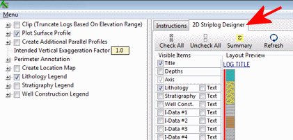
- Visible Items: Use the check-boxes in the Visible Items column to select which log items are to be displayed. See Visible Item Summary for information about the different log items.
- Options: Click on any of the Visible Items names to see the item's settings in the Options pane to the right. See the Visible Item Summary for links to the Options settings.
- Layout Preview: For each item you've activated, you'll see a preview cartoon in the upper pane. Click and drag any item to the left or right to rearrange the log columns. See Using the 2D Log Designer.
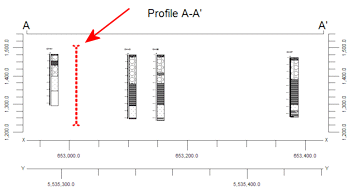
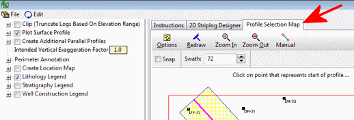
- Profile Selection Map: Click on the Profile Selection Map tab to the right, to select where the profile cut (or multiple cuts, if you've requested parallel profiles, above) to be placed. The most recent profile drawn for this project will be displayed. (More.)
- Rules and Filters: Use the settings on the far right side of the window to apply stratigraphic rules, date filters, and/or spatial filters to data being displayed in your logs. (More.)
Step-by-Step Summary
Follow these steps to create a 2D diagram that illustrates multiple strip logs projected onto a single profile line.
- Access the Borehole Manager program tab.
- Enter/import your data into the Borehole Manager database.
- Select the Borehole Manager | Striplogs | 2-Dimensional | Profile command.
- Establish the log settings, as described above.
- Be sure to click on the 2D Striplog Designer tab to establish how you want the logs to look.
- Be sure to click on the Profile Selection Map tab to set the profile location.
- Click on the Process button at the bottom of the window to create the striplog profile diagram.
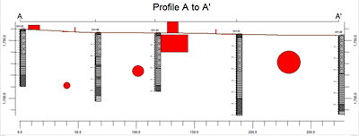
The program will create an individual strip log of those borings that were flagged as enabled and which were included in any distance clipping. Only the log items you have activated will be displayed in the logs. The logs will be "projected" perpendicularly onto the profile line cut, and any additional diagram settings that you requested will be included. The profile will be displayed in a RockPlot2D tab in the Options window.
- You can adjust any of the following items and then click the Process button again to regenerate the profile.
- Profile settings in the Options pane on the left, and/or
- Rules and Filter settings in the pane to the right, and/or
- Striplog settings in the 2D Striplog Designer tab, and/or
- Profile location in the Profile Selection Map tab.
! Each time you click the Process button (or the <Enter> key on your keyboard), the existing display will be replaced.
! Tip: You can undock the plot window using the  button.
- View / save / manipulate / print / export the profile in the RockPlot2D window.
Tip: If logs or portions or logs are missing, you should check the clipping distance that was established in the Profile Selection Map window. If even a portion of a log is not included in the clipping rectangle, it will not be shown in the sections. You may need to use its Zoom tool to enlarge the view for better resolution.
 Back to StripLogs Menu Summary

RockWare home page