RockWorks | Utilities | Imagery |
Vertical (Images -> 3D Panels )
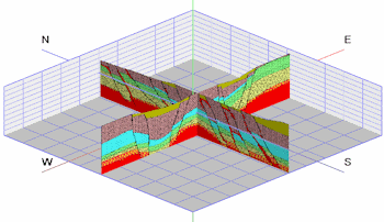
Use this program to display vertical bitmaps representing hand-drawn sections, seismic sections, GPR profiles, etc. in three-dimensions.
See also:
Menu Options
Step-by-Step Summary
Menu Options
- Specify the datasheet Input Columns in the left pane of the window.
- File Name: Select the column that lists the name(s) of the raster image(s) to be shown on panels. Supported file formats are shown above.
Tip: use the File | Import | Create File List program to quickly create a list of specified file names.
- Layer Name: Select the column in which the layer names are listed. These will simply be used to label the panels in RockPlot3D.
- X Lower-Left, Y Lower-Left, Z Lower-Left: Select the three columns in the datasheet that list the Easting, Northing, and elevation coordinates for the lower-left corner of the bitmap.
These can be defined in your project coordinates or other coordinate system. See Defining your Datasheet Coordinates for more information.
- X Upper-right, Y Upper-right, Z Upper-right: Select the three columns that list the Easting, Northing, and elevation coordinates for the upper-right corner of the bitmap.
- Group Name: Click here, in the right pane of the window, to enter a name for the panel group in RockPlot3D. For example, if all of the panels represent 2D seismic scans, you could name this "Seismic Panels".
- Set Transparent Color: Insert a check in this box if you want to specify a specific color in the bitmap images to be displayed transparent. For example if the images have a white background and you would like that part to be see-through, you would select white. This color will be applied to all of the images.
If activated, expand this heading to click on the color box to choose the image color that is to be set to transparent.
- Reference Cage: Insert a check here to include reference labels or lines in the output 3D image. More.
Step-by-Step Summary
- Access the RockWorks Utilities program tab.
- Open a data file that contains a listing of bitmap image names and their lower-left and upper-right real-world coordinates. These could be, for example, scanned images of 2D seismic or ground penetrating radar sections.
- Select the Imagery | Vertical (Images -> 3D Panels) menu option.
- Enter the menu settings as described above.
- Click the Process button to continue.
The program will read the indicated bitmap image(s), assign them the indicated coordinates, and display them as vertical panels in a RockPlot3D tab in the Options window.
- You can adjust any of the options along the left (such as transparent color) and click the Process button to regenerate the 3D image.
! Each time you click the Process button, the existing display will be replaced.
- View / save / manipulate / print / export the image in the RockPlot3D window.
 Back to Imagery Menu Summary

RockWare home page