 Estimated time: 2 minutes.
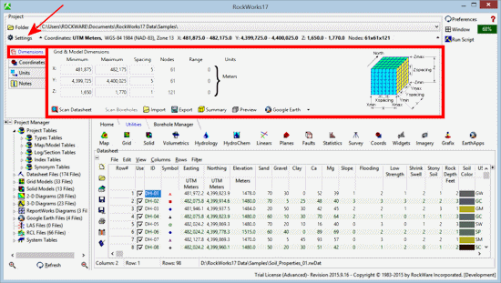
Each time you start a new project in RockWorks, you need to establish the dimensions for RockWorks so that there will be consistency in how models and diagrams are dimensioned.
- Locate the Project | Settings button at the top of the program window. Click on that to access the Output Dimensions pane.
Notes:
-
- The Project Coordinate system and units, shown in the Coordinates button, are already established. These are defined when a project folder is first created. For this Samples project, the project space is defined as UTM meters (NAD-83, Zone 13).
- The Grid & Model Dimensions are the actual coordinate values that represent:
- The extents of the project space: western, eastern, southern, northern, base elevation, and top elevation coordinate boundaries.
- The spacing of the nodes which will determine the density of grid models (XY) and solid models (XYZ) that you interpolate.
You can establish the Grid & Model Dimensions by typing in the coordinate values. Or you can use the Scan Datasheet button which is displayed at the bottom of the pane.
In your own work, the Scan Datasheet button is the easiest method to quickly establish coordinate extents. For this project, we'll just have you confirm that the existing coordinates are correct.
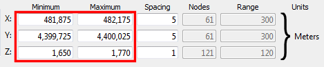
- Confirm the Min and Max Coordinates: Be sure these are set as shown here; you can type in the numbers as necessary.
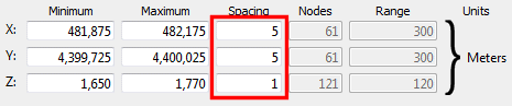
- Set the Node Spacing:
- X-Spacing: Be sure this prompt is set to: 5. This means that there will be a model node placed every 5 meters from west to east across the project space. This will generate 61 nodes from west to east in the models. You’ll note that when you change the Spacing setting, the number of nodes represented will be updated automatically.
- Y-Spacing: Type in: 5. This will generate 61 nodes from south to north in the models, also at a 5-meter spacing.
- Z-spacing: Type in: 1. This means that the nodes will be 1 meter apart from the base of the project to the top.
! In your own work, the appropriate node spacing will depend on the spacing of your wells and downhole measurements. See How Dense is Dense Enough for some tips.
! The output dimensions settings are stored in the project database, and are loaded each time you access that project folder.
 Viewing and Setting Your Output Dimensions
 Back to map menu | Next (point map)

RockWare home page