! Notes: Fault-bounded modeling is considerably slower than non-fault modeling by orders of magnitude (e.g. hours versus minutes). This is especially true if you have created your 3D Fault File using the "Complex" method (multiple vertices) rather than the "Simple" method.
Faulting requires RockWorks Advanced.
Click on the Faulted tab to access the settings.
- 3D Fault File: Click to the right to browse for the RwFlt file which you have already created, containing the fault definitions.
To create your 3D Fault File for one fault, you need to list the fault polyline vertex locations, dip angle, and dip direction in the Utilities datasheet and use the Faults | Single Dip List -> 3D Fault File program to generate the RwFlt file. See Creating 3D Fault Files - Single Faults for information.
To create your 3D Fault File for multiple faults, you need to create individual RwDat files with locations, dip angle, and dip direction for each fault. Then list these RwDat file names in the current Utilities datasheet and use the Faults | Multiple Dip Lists -> 3D Fault File program to generate the RwFlt file. See Creating 3D Fault Files - Multiple Faults for details.
- Assign G Values to Fault Nodes: Insert a check here to assign specific "G" values to the model nodes which lie along the fault planes.
- Fault Node G-Value: Type into the prompt the value to be assigned to the nodes which lie along the fault plane.
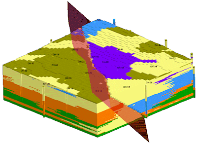
Tip: Plotting a semi-transparent dip-ribbon (also in the Utilities Faults menu) in conjunction with the block model can be a useful way to highlight fault discontinuities.