RockWorks | Utilities | Solid | Filters | Tube Filter
Given a list of xyz coordinates that represent the axes of tubes (e.g. mine workings, tunnels, etc.), this program will either set all nodes for a designated solid model (e.g. ore grades, lithologies, porosity) outside or inside the tubes to a null value. For example, a tunneling operation could use this program to compute the volumes of various materials that are to be extracted from the tunnel(s). Conversely, a mining resource model could be subjected to a tube-filter whereby the mined regions, modeled by tubes, are removed from the model by setting the regions within the tubes to a null value.
The input file for the Tube-Filter program is identical to that used by the Grafix | 3D-Utilities | Tubes program. An example is provided by the "tubes_01.rwDat" sample file.
Menu Options
Step-by-Step Summary
Menu Options
- Input Columns: Select the columns from the left pane of the window:
- X1: Click on the X1 item to select the name of the datasheet column that contains the X or Easting coordinate for one end of the tube.
These coordinates can be in meters or feet, local coordinates, etc. See Defining your Datasheet Coordinates for more information.
- Y1: Click on the Y1 item to select the name of the datasheet column that contains the Y or Northing coordinate for one end of the tube
- Z1: Click on the Z1 item to select the name of the datasheet column that contains the Z or elevation coordinate for one end of the tube.
- X2: Click on the X2 item to select the name of the datasheet column that contains the X or Easting coordinate for the other end of the tube.
- Y2: Click on the Y2 item to select the name of the datasheet column that contains the Y or Northing coordinate for the other end of the tube.
- Z2: Click on the Z2 item to select the name of the datasheet column that contains the Z or elevation coordinate for the other end of the tube.
- Input Model: Click to the right to browse for the name of the existing RockWorks solid model (*.RwMod file) to be filtered.
- Output Model: Click to the right to type in the name to assign to the new solid model that the program will create, which results from the filtering operation.
- Filter Style:
- Choose Nullify Interior Nodes if all model nodes that lie inside the tunnels are to be set to a null value.
- Choose Nullify Exterior Nodes if all model nodes that lie outside the tunnels are to be set to the null value.
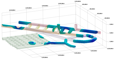
- Create 3-Dimensional Diagram: Insert a check here if you want to create a plottable 3D diagram of the resulting solid model. Expand this item to establish the diagram settings.
- Diagram Type: Choose Isosurface to display the solid model as if enclosed in a "skin". Choose All Voxels to display color-coded voxels. (More.)
- Iso-Mesh: Use this option to plot a series of polylines that represent three-dimensional contours at a user-defined cutoff. Expand the heading to establish the settings. (More.)
- Color Scheme: Click on the Options button to the right to access a variety of pre-set color schemes, or to create your own. (More.)
- Reference Cage: Insert a check here to include vertical elevation axes and X and Y coordinate axes in the 3D diagram. Expand this item to set up the cage items. (More.)
- Include Legend: Insert a check here to include an index to the colors and G values in the diagram. (More.)
Step-by-Step Summary
- Access the RockWorks Utilities program tab.
- Open or create a data file that contains a listing of XYZ coordinates for each tube end.
- Select the Solid | Filters | Tube Filter menu option.
- Specify the menu settings, described above.
- Click the Process button to continue.
The program will read the contents of the input solid model file and compare the location of each of its nodes to the tubes you have defined, and replace the interior or exterior nodes (as requested) with a null value. The resulting solid model file will be stored under the declared output file name. If you have requested a diagram, it will be displayed in a RockPlot3D tab.
- You can adjust any of the input options along the left side of the window and click the Process button again to regenerate the model and display.
! Each time you click the Process button, the existing 3D display will be replaced.
- View / save / manipulate / print the image in the RockPlot3D window.
 Back to Solid Menu Summary

RockWare home page