RockWorks | Utilities | Solid | Filters | Borehole Filter
Use this program to create one or more tunnels (or mine drifts) through a solid model, using borehole location coordinates and downhole survey information for the active boreholes in the Borehole Manager. Specifically, this tool defines the tunnel starting point as a borehole collar XYZ and then uses the downhole survey information in the Orientation tab for the tunnel survey.
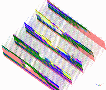
This program can be used to either nullify the voxels outside or inside of the tunnel(s). For example, a tunneling operation could use this program to compute the volumes of various materials that are to be extracted from the tunnel(s). Conversely, a mining resource model could be subjected to a tube-filter whereby the mined regions, modeled by tubes, are removed from the model by setting the regions within the tubes to a null value. The graphic example above illustrates a single horizontally-trending borehole through a lithology model, which is viewed as a cloud of points with 5 north-south slices. The nullified interior nodes can be seen as holes in the panels and as the ghost trace through the points.
This program operates similarly to the Tube Filter option, except that it pulls the tube location(s) from the active borehole(s) in the Borehole Manager database rather than from a listing in the Utilities datasheet.
Menu Options
Step-by-Step Summary
Menu Options
- Input Model: Click to the right to select the name of the existing RockWorks solid model file (*.RwMod) to be filtered.
- Output Model: Click to the right to type in the name to assign to the new solid model that the program will create, which results from the filtering operation.
- Borehole Radii: Click here to type in the radius of the tubes in units that match the XYZ units of the solid model. For example, if your solid model units represent feet, then you would enter the radius of the tubes in feet.
- Filter Style:
- Choose Nullify Interior Nodes if all model nodes that lie inside the boreholes are to be set to a null value.
- Choose Nullify Exterior Nodes if all model nodes that lie outside the boreholes are to be set to the null value.
- Null Value: Use this prompt to define the replacement value for the filtered nodes. The default RockWorks null value is -1e27; you can enter this value or define a different replacement value.
- Create 3-Dimensional Diagram: Insert a check here if you want to create a plottable 3D diagram of the resulting solid model. Expand this item to establish the diagram settings.
- Diagram Type: Choose Isosurface to display the solid model as if enclosed in a "skin". Choose All Voxels to display color-coded voxels. (More.)
- Iso-Mesh: Use this option to plot a series of polylines that represent three-dimensional contours at a user-defined cutoff. Expand the heading to establish the settings. (More.)
- Color Scheme: Click on the Options button to the right to access a variety of pre-set color schemes, or to create your own. (More.)
- Reference Cage: Insert a check here to include vertical elevation axes and X and Y coordinate axes in the 3D diagram. Expand this item to set up the cage items. (More.)
- Include Legend: Insert a check here to include an index to the colors and G values in the diagram. (More.)
Step-by-Step Summary
- In the Borehole Manager of the program be sure only those borehole(s) to be used to filter the solid model are currently enabled (shown with check-marks).
- Access the RockWorks Utilities program tab.
- Select the Solid | Filters | Borehole Filters menu option.
- Specify the menu settings, described above.
- Click the Process button to proceed.
The program will read the contents of the input solid model file and compare the location of each of its nodes to the enabled boreholes, and replace the interior or exterior nodes (as requested) with a null value. The resulting solid model file will be stored under the declared output file name. If you have requested a diagram, it will be displayed in a RockPlot3D tab.
- You can adjust any of the input options along the left side of the window and click the Process button again to regenerate the display.
! Each time you click the Process button, the existing 3D display will be replaced.
- View / save / manipulate / print the image in the RockPlot3D window.
 Back to Solid Menu Summary

RockWare home page