RockWorks | Utilities | Planes | Strike & Dip Diagram (3D)
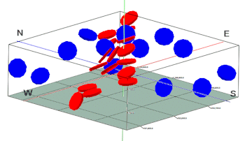
This program reads XYZ locations and strike and dip measurements from the datasheet, and represents them in 3D space as oriented disks. These discs may represent fractures or other oriented planar features.
Menu Options
Step-by-Step Summary
Menu Options
- Input Columns: The prompts along the left side of the window tell RockWorks which columns in the input datasheet contain what data.
Click on an existing name to select a different name from the drop-down list.
- Title: Choose the column in the datasheet, if any, that lists the name or title to be plotted next to each disk.
- X: Column that contains the X or Easting coordinates for the sample locations.
These can be Eastings in meters or feet, decimal longitudes, etc. See Defining your Datasheet Coordinates for more information.
- Y: Column that contains the Y or Northing coordinates for the points.
- Z: Column that contains the elevations where the measurements were taken and where the disks should plot. Be sure you've defined the elevation units in the column heading.
- Dip Direction: Choose the column that lists the direction, in degrees, that disk is dipping. North = 0, East = 90, South = 180, and West = 270. Note: This is the direction of maximum dip. It is NOT the "strike".
- Dip Angle: Choose the column that lists the dip angle. Note: Horizontal is considered to be zero, and dipping straight down is entered as 90.
- Group Name: Enter the name for the fracture disks grouping in RockPlot3D, such as "fracture disks". You can change the name once the disks are displayed in RockPlot3D.
- Radii: The radii of the disks can be defined in one of two ways; expand this heading if necessary to make a selection:
-
- Fixed: The "Fixed" setting will plot all of the disks using the same, user-defined radius setting. Expand this heading to enter the Radius size.
-
- Radius: The "Radius" setting determines the diameter for all disks. Enter the value in your output units.
- Variable (Defined by Column): Choose this option to plot each disk using the radius setting which is defined within the datasheet.
-
- Radius Column: Select the column in which the disk radii are listed. Be sure you've defined the data units (e.g. feet or meters) in the column heading.
- Multiplier: To universally scale the disks up or down, you can enter a value other than "1" which, when multiplied by the declared radius values, will determine the disk size.
- Aperture: The thickness of the disks can be defined in one of two ways; expand this heading if necessary to make a selection:
-
- Fixed: The "Fixed" setting will plot all of the disks using the same, user-defined thickness setting. Expand this heading to enter the Aperture size.
-
- Aperture: Enter the thickness for all disks, in your output units.
- Variable (Defined by Column): Choose this option to plot each disk using thickness values which are listed within a column in the datasheet.
- Aperture Column: Select the column in which the disk thicknesses are listed. Be sure you've defined the data units (e.g. feet or meters) in the column heading.
- Multiplier: To universally scale the disks to be thickner or thinner, you can enter a value other than "1" which, when multiplied by the declared aperture values, will determine the disk thickness.
- Color: Like the above settings, the color of the disks can be defined as fixed or variable; expand this heading if necessary to make a selection.
-
- Fixed: The "Fixed" setting will plot all of the disks using the same, user-defined color. Expand this heading to choose the color.
-
- Color: Click on the color box to choose the color for all of the 3D disks.
- Variable (Defined by Column): Choose this option to plot each disk using the colors which are listed in the datasheet.
- Color Column: Select the name of the column in which the colors are listed.
- Stretch with Vertical Exaggeration: Insert a check here if you want the dip angles of the disks to change as the vertical exaggeration changes while still honoring the relative spatial relationships. Leave this un-checked if the disk angles should remain constant.

Step-by-Step Summary
- Access the Utilities program tab.
- Create a new datasheet and enter/import your dip-direction/dip-angle data into the datasheet.
Or, open one of the sample files and replace that data with your own. (In the Samples folder, an example file = "\RockWorks17 Data\ Samples\Strike_and_Dip_3D_01.rwDat".)
- Select the Utilities | Planes | Strike & Dip Diagram (3D) menu command.
- Enter the requested menu options, described above.
- Click the Process button to continue.
The program will read the indicated XYZ location coordinates and plot a disk at the selected dip direction and angle, using the fixed or variable size and color settings you specified. The diagram will be displayed in a RockPlot3D tab in the Options window.
- You can adjust any of the options along the left and click the Process button to regenerate the display.
! Each time you click the Process button, the existing display will be replaced.
- View / save / manipulate / print / export the image in the RockPlot3D window.
See also: Changing Column Titles, Styles, and Units
 Back to Planes Menu Summary

RockWare home page