RockWorks | Utilities | Map | Infrastructure | 3-Dimensional Diagram
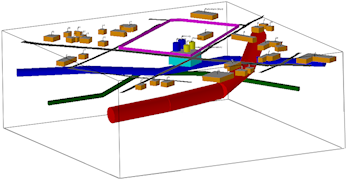
This program is used to create simple 3D entities such as buildings, roads, tanks, and walls that may be plotted in conjunction with other three-dimensional diagrams. The input for the 3D Infrastructure program consists of a text file that contains a series of objects and parameters.
These infrastructure objects can also be displayed as a 2D map and in cross section diagrams.
This program replaces the Grafix | Surface Objects program in earlier versions of RockWorks.
Menu Options
Step-by-Step Summary
Menu Options
- Input Options
- (ASCII) File: Click on this item to select the name of the user-created text file that contains the listing of infrastructure object and parameter commands.
- Plot Object Labels: Check this item to include object labels in the output display.
- Reference Cage: Insert a check here to include vertical elevation axes and X and Y coordinate axes in the 3D diagram. Click on the Options button to set up the cage items. (More.)
Step-by-Step Summary
- Create your external text file that contains the "Building", " Road", and other infrastructure commands, using Notepad or another program capable of saving documents as text-only. See Infrastructure Data Format for details. See the "Infrastructure_xx.txt" files in the RockWorks17 Data\Samples folder for examples of this type of file.
- Access the RockWorks Utilities program tab. This tool does not read data from the main data window.
- Select the Map | Infrastructure | 3-Dimensional Diagram menu option.
- Enter the requested menu settings, described above.
- Click the Process button to continue.
The program will read the commands within the text file and build the shapes at the designated fixed or grid-based elevations. The completed image will be displayed in a RockPlot3D tab in the Options window.
- You can adjust any of the options along the left and click the Process button to regenerate the 3D image.
! Each time you click the Process button, the existing display will be replaced.
- View / save / manipulate / print / export the image in the RockPlot3D window.
Tip: Use RockPlot3D’s File | Save As to save the view of the infrastructure objects, then use File | Append to append another existing RockPlot3D view (stratigraphic model, isosurface, etc.) to this image.

 Back to Map Menu Summary

RockWare home page