A 2D Fault is defined as an individual line segment or as as an individual polyline, within the Faults tab in the project database.
! Unlike earlier versions of RockWorks, both 2D and 3D faults are stored in the Faults tab. The number of faults you can store in your project is defined by the feature level of your license: 3 faults for Basic and Standard, unlimited faults for Advanced.
A 2D Fault can be created in several ways:
- Converting a single line segment, importing a polyline from the datasheet, or importing from a RockWorks16/17 fault table. These are in the Faults tab Import menu and are discussed in that topic.
- By drawing the lines or polylines onto a map displayed in RockPlot2D, and copying them to the Faults tab. This is discussed here.
Step-by-Step Fault Example:
- We begin by creating a unfaulted grid model and contour map by using the RockWorks | ModOps | Grid | Create | XYZ -> Grid program. (You could also use any of the other contour mapping programs in RockWorks.)
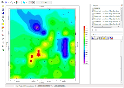
Unfaulted grid model and diagram displayed within RockPlot2D.
- Next, we select the Draw | Polyline tool in RockPlot2D and draw, on-screen, the interpreted fault traces. Each polyline can be completed by double-clicking.
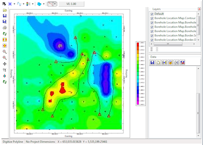
Polylines drawn on-screen using the Draw | Polyline tool within the RockPlot2D program.
- When you've drawn all of the lines, select the Edit Mode button
 in the RockPlot2D toolbar. This takes you out of polyline-drawing mode.
- Save the polylines to the Faults table.
- Click on one polyline to select it. You will see handles on its vertices.
- Right-click on the selected polyline, and choose Save to Faults Table in the pop-up menu.
- Enter a name for this new table, and assign the properties to the fault, and click OK. You should be descriptive with your names for future identification. (You can maintain multiple Fault Tables in a project database.)
! If a Fault Table by that name already exists, its contents will be replaced by this new polyline information.
- Repeat this process for the other polylines you drew.
- Now, you'll need to recreate the grid model, with the faulting option activated. But first, minimize the map window and click on the Faults tab in the main RockWorks screen. Be sure the faults you wish to apply to the modeling are checked (active).
- Return to the map window and click on the Options tab (upper-left) to return to the map settings. Make the following changes to the menu settings:
- In the Grid Model | Options tab, activate the Faulted option. There are no options to set here - it will apply all of the faults that are currently active.
- In the 2D Grid Map tab, insert a check in the Map Overlays option. Check the Faults sub-option and establish the fault map settings.
- Click the Continue button to reinterpolate the grid model, and regenerate the map.
The new map should look something like the following:
Map representing faulted grid model.
NOTE: This faulting capability can also be used to simulate non-fault discontinuities such as erosional and excavation escarpments.
Topographic Model Using Fault Capability To Depict Excavation Breakpoints

RockWare home page