Faults | Import | Contours -> 3D Fault Mesh
Use this program to (1) read from the RockWorks Datasheet two or more polylines that represent contours along a fault surface, (2) generate a 3D fault surface from the polylines, and (3) store the fault in the project Fault table.
Caveats/Conventions:
- The polyline data must be listed in the same order for each polyline. For example, if a north/south polyline was digitized from south to north, the other polylines must be digitized in the same order.
- The program can only create one 3D fault per RwDat file. If you have more than one fault surface, they must be processed separately and stored as separate faults.
- ! The number of faults you can maintain in your project is determined by the feature level of the software:
- Basic: 3 Faults
- Standard: 10 Faults
- Advanced: Unlimited Faults
Menu Options
Step-by-Step Summary
- Data Columns: Use this tab to define the columns in the datasheet where the input polyline data is listed:
- X (Easting): Choose the column containing the polyline X-coordinates.
- Y (Northing): Select the column where the polyline Y-coordinates are listed.
- Z (Elevation): Select the column containing the polyline elevations.
- Attributes: Use these settings to establish general fault and display settings. These will be stored with the fault in the database and can be accessed/edited using the Edit Fault button in the Faults tab.
- Fault Name: Enter the name to assign to the fault, to distinguish it from other faults. This is displayed in the Name column in the Faults table, and can be displayed as labels on the fault polylines.
- G-Value: Assign a G-Value to the fault. This is assigned to model nodes that intersect the fault triangles.
- Comment: Use this optional field to list any descriptive comments for the fault, for your reference only.
- Line Style: Choose a line color and style with which to represent the fault in 2D maps and sections, and as a polyline in 3D.
- Fill Color: Assign a Fill Color for the fault panels when displayed in 3D.
- Line Symbols: Use these settings to define the symbol style if, during 2D map creation, if you choose to include symbol along the fault polyline.
- Symbol Line Thickness: Click the up/down arrows to assign a thickness for the lines which will make up the fault symbols. "1" will generate thin lines, "3" relatively thick lines.
- Type of Symbol: Choose a symbol type from the drop-down list. If you choose a Custom type, click to the right to select the custom symbol design.
- Access the RockWorks Datasheet program tab.
- Open a data file that contains a listing of polyline XYZ coordinates.
- Click on the Faults program tab.
- Select the Faults | Import | Contours -> 3D Fault Mesh menu option.
- Enter the requested menu settings, described above.
- Click the Continue button to proceed.
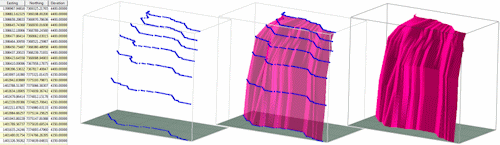
RockWorks will read the listed polylines and resample each such that every polyline has the same number of vertices. It will then construct triangles between adjacent contours, generating a 3D fault mesh. The completed fault surface will be stored in the project Fault table.
- You can now use this fault, along with other enabled faults in the Fault table, when creating a surface model or solid model and applying faulting.
 Back to Faults Program Tab

RockWare home page