RockWorks | Utilities | Volumetrics | Extract Solid
This program reads an existing solid model (such as soil chemistry or lithology type), determines the volume of a pit that would be required to extract the portions of the solid model that fall within a specified range (e.g. contaminated soil or a selected lithotype). The program allows you to specify the name of a surface grid model so that the final diagram is not based on a flat surface.
The output is a report that lists the pit and contaminant volumes and the stripping ratios, a 2D diagram illustrating the pit elevations, and/or a 3D diagram showing the filtered solid and the pit elevations.
This program assumes you have already created a solid model that illustrates the distribution of the desired material. This can be created using the Utilities | Solid | Model tool (for XYZG data in the datasheet or external file) or using the Borehole Manager Model tools (Lithology, Stratigraphy, P-Data, I-Data menus). You may also input solid models that have already been filtered for G value range or with a polygon filter (Solid | Boolean Ops or Solid | Filter tools).
This program also assumes that you have already created a grid model of the surface topography that will be used when modeling the pit. The surface grid model must have the same dimensions and node counts as the X and Y dimensions of the input solid model.
This extraction process assumes that the excavation walls are vertical (no benches or slopes). (You can refer to the RockWorks support web site for a white paper describing a sand and gravel excavation project in which benches are inserted.)
Menu Options
Step-by-Step Summary
Menu Options
- Pre-Excavation Models:
- Ground Surface (Grid): Click on this prompt to locate the name of the existing RockWorks grid file (.RwGrd) that represents the surface topography, in elevations, for the solid model to be processed. The grid must have the same dimensions and number of nodes as the solid model in the west <-> east and south <-> north directions. The program will use this surface to more accurately drape the output grid and represent computed volumes.
- Ore/Contaminant Grade (Solid): Click on this prompt to browse for the existing solid model to be filtered. This model can represent lithology types, soil geochemistry, etc. This file should have an .RwMod file name extension.
- Post-Excavation Models:
- Ground Surface (Grid): Click on this prompt to enter a name for the grid model (.RwGrd file) that the program will create. This model will represent the surface elevations of the extraction pit.
- Ore/Waste/Air (Solid): Click here to type in a name to assign to the filtered solid model (.RwMod file). This will be a real-number solid model, not a Boolean model.
- Thresholds: Expand this heading to specify the range of G values in the solid model to be extracted. If you are using an I-data or P-data model from the Borehole Manager, the thresholds will be entered as real number values. If you are using a Borehole Manager lithology model, the thresholds should be real numbers on either side of the integer lithology value to be extracted. If you are using a Boolean model, the thresholds should represent "0" or "1".
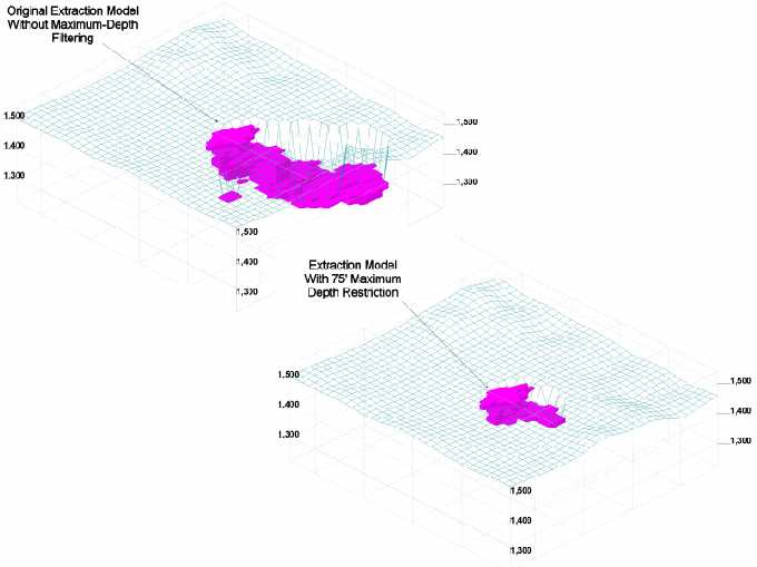
- Maximum Depth Filter: Insert a check here to specify the maximum extraction depth relative to the surface. This setting is also shown (if enabled) within the statistical report. The units must match your output elevation units.
- Maximum Slope: Click on this settings to specify the maximum slope angle for the excavation surface (pit). Slope angles must be expressed in negative degrees from -90 to zero. For example, -90 = vertical walls.

- Add Benches: Check this option if benches are to be added to the excavation pit.
- Bench Height: Type in the height for the benches, in your output elevation units.
- Add Buffer: This option allows you to specify a "buffer" around the perimeter of the ore/contaminant nodes such that the entire voxel will be removed (versus just a pit that encloses the node). This is accomplished by enlarging the excavation pit such that there will be a one-voxel border around the lateral sides of each voxel.

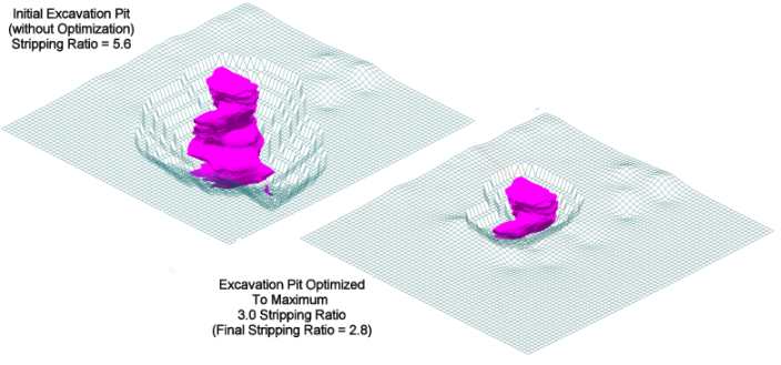
- Optimize: If activated, this option will start by computing the configuration for a pit that extracts all of the material within the specified grade range. It will then decrease the maximum pit depth (by the increments specified by the "Depth Increment" setting) until the stripping ratio is equal to or less than the specified "Maximum Acceptable Stripping Ratio".
- Material Density: This setting is used to convert volume (in cubic feet or meters, depending on your X, Y, and depth units ) to mass, to result in pounds or kilograms or tons per cubic foot or meter.
- Report Captions: Expand this heading to enter the text for the extraction report so that it makes sense for your project: In this example, you can use the text colors shown below to match the report item to the report example at the end of this topic.
- Cutoff Units: This represents the G value units in the model for which you are filtering. For example, if the model represents soil contamination concentrations of PCB’s in parts per million, you could enter ppm.
- Target name: This represents the name of what the G values represent in the model, such as PCB for the above soil contamination example. For a lithologic model, it could be "clay".
- Pit Name: This is the name you can assign to the pit itself, such as Soil Remediation.
- Length Units: Enter Feet or Meters, depending on the units of your X and Y coordinates and elevations.
- Mass Units: Enter Pounds or Kilos or Tons or whatever is appropriate based on the Material Density you entered above.
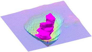
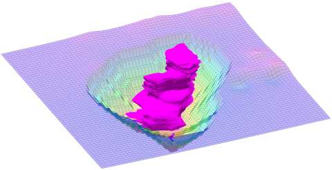
- Create 3-Dimensional Diagram: Insert a check in this box if you want to create a 3D diagram of the filtered model with the extraction surface (or "pit"). Expand this to set the diagram options.
- Diagram Type: Choose from:
- All Voxels: Click in the All Voxels radio button to represent the solid model in the 3D display as color-coded voxels.
- Isosurface: Click in the Isosurface radio button to display the solid model as if enclosed in a "skin."
- Reference Cage: Insert a check here to include vertical elevation axes and X and Y coordinate axes in the 3D diagram. Expand this item to set up the cage items. (More.)
- Include Legend: Insert a check here to include an index to the colors and G values in the diagram. (More.)
- Post-Extraction Surface (Pit) Model
- Create 2-Dimensional Grid Diagram: Insert a check in this box if you want to create a 2D representation of the extracted grid or pit surface. The units in the model represent elevations. Expand this heading to establish the 2D map settings. (More.)
-
- Create 2-Dimensional Grid Diagram: Click here to request a 3D image of the extracted pit surface. Expand this heading to establish the 3D map settings. (More.)
- Create Grid Statistics Report: Insert a check here if you want to see a report summarizing the output grid.
Step-by-Step Summary
- Access the RockWorks Utilities program tab.
- Select the Volumetrics | Extract Solid menu option.
- Enter the requested model, filter, and diagram settings, described above.
- Click the Process button at the bottom of the Extract Solid Options window to proceed.
The program will read the input solid model and determine those voxels that fall within the declared thresholds. It will determine the extent of a vertical-wall pit for extraction of these solid model areas. It will compute total extracted volume, total solid model volume, and stripping ratio (overburden:solid).
If requested, the report will be displayed in a text tab in the Options window. (See Example, below.) The requested diagram(s) will be displayed in a RockPlot2D tab and/or RockPlot3D tab in the Options window.
- You can adjust any of the settings in the Options window and then click the Process button again to regenerate the diagram(s).
! Each time you click the Process button, the existing display(s) will be replaced.
- View / save / manipulate / export / print the diagram in the RockPlot2D or RockPlot3D window.
Example
Solid Extraction Statistics
---------------------------
PCB Volume ... 37,132 Cubic Feet
PCB Mass ..... 427.0 Tons
Soil remediation site Volume ... 331,777 Cubic Feet
Soil remediation site Mass ..... 3,815.4 Tons
Maximum Soil remediation site Depth: 25.6 Feet
Stripping Ratio: 8.935:1
Assumptions:
- Initial ground surface is assumed to be flat.
- Excavation walls are vertical (no benches or slopes).
- PCB volume based on the following cutoff values;
Minimum PCB Value: 0.5 ppm
Maximum PCB Value: 9,999.0 ppm
- Density Conversion Factor: 0.0115 Tons Per Cubic Feet
See also
 Back to Volumetrics Menu Summary

RockWare home page