RockWorks | Utilities | Solid | Math | Merge Models
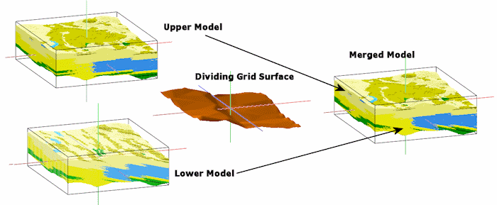
This program reads two existing solid models (.RwMod files) and either a plane or a grid surface (.RwGrd file), and creates a new model in which the upper portion is based on one of the originals, and the lower portion is based on the other.
This feature allows you to model different parts of your geology using different techniques. In the graphic example above, the upper lithology model represents regular (horizontally-biased) interpolation, and the lower was generated with a regional tilt. Merging these models using a surface delineating the discontinuity permits the model to show the two different techniques.
! The solid models and the grid model must have the same dimensions.
Menu Options
Step-by-Step Summary
Menu Options
- Top Model: Click to the right to browse for the name of the existing RockWorks solid model file (.RwMod file) whose nodes are to be used for the upper part of the output model.
- Base Model: Click to the right to browse for the name of the existing solid model file (.RwMod file) whose nodes are to be used for the lower part of the output model.
- Merged Model: Click to the right to type in a name for the output solid model file (.RwMod) which will contain the merged model.
- Grid Based: Click in this radio button if you wish to use an existing grid model (.RwGrd) as the model divider. Expand this heading as necessary.
- Dividing Grid: Click here to browse for the name of the existing grid model to be used as the dividing grid.
- Plan Based: Click in this radio button if you wish to use a planar surface as the model divider.
- Grid Name: Click here to enter a name for the .RwGrd file which will be initialized as you define here, and saved as a grid model.
- Model Dimensions: Expand this heading to set the grid dimensions.
! Remember that this model must have the same X,Y dimensions as the solid models being merged.
- Orientation: The new divider grid model can be either a horizontal or inclined plane.
- Horizontal: Choose this option to set all nodes such that grid represents a horizontal plane.
- Elevation: Value to assign to all nodes within the grid model.
- Inclined: Choose this option to tilt the plane based on user-defined parameters.
- Dip Direction: Dip direction of the plane, in degrees. 0 = North. 90 = East. 180 = West.
- Dip Amount: Dip angle of the plane, in degrees. 0 = horizontal, -90 straight down. 90 = straight up.
- Reference Point: The output model will be adjusted such that the inclined plane intersects this point.
- X: Easting at reference point.
- Y: Northing at reference point.
- Z: Elevation at reference point.
- Create 3-Dimensional Diagram: Insert a check here if you want to create a plottable 3D diagram of the resulting solid model. Expand this item to establish the diagram settings.
- Diagram Type: Choose Isosurface to display the solid model as if enclosed in a "skin". Choose All Voxels to display color-coded voxels. (More.)
- Iso-Mesh: Use this option to plot a series of polylines that represent three-dimensional contours at a user-defined cutoff. Expand the heading to establish the settings. (More.)
- Color Scheme: Click on the Options button to the right to access a variety of pre-set color schemes, or to create your own. (More.)
- Reference Cage: Insert a check here to include vertical elevation axes and X and Y coordinate axes in the 3D diagram. Expand this item to set up the cage items. (More.)
- Include Legend: Insert a check here to include an index to the colors and G values in the diagram. (More.)
Step-by-Step Summary
- Access the RockWorks Utilities program tab. This tool does not require that any data be displayed in the datasheet.
- Select the Solid | Math | Merge Models menu option.
- Enter the requested menu settings, described above.
- Click the Process button to continue.
The program will load the input solid model files, determine the nodes in the Top Model that lie above the divider grid, and determine the nodes in the Base Model that lie below the divider grid. Those node values will be copied to the output model.
If you requested a diagram, it will be displayed in a RockPlot3D tab in the Options window, using the requested display type.
- You can adjust any of the input settings or diagram options in the Options pane to the left, and then click the Process button again to regenerate the display.
! Each time you click the Process button, the existing 3D display will be replaced.
- View / save / manipulate / print / export the model in the RockPlot3D window.
 Back to Solid Menu Summary

RockWare home page