
RockWorks | Utilities | Solid | Filters | Smoothing Filter
This program reads an existing solid model and averages the G-values based on a user declared "filter" size. The smoother can be run 1 or more times, to get rid of spurious "noise" within the model and bring out regional trends. Two smoothing methods are offered, and specific node values can be flagged exempt from smoothing.
Menu Options
Step-by-Step Summary
Menu Options
- Input Model: Click to the right to browse for the name of the existing RockWorks solid model (.RwMod file) that the program is to read and filter.
- Output Model: Click to the right to type in the name to assign to the new solid model that the program will create, which results from the smoothing operation.
- Filter Size: Expand this item to establish the horizontal and vertical filter size, which define how many adjacent nodes should be used when computing the average (smoothed) G-value for each model node. See the program window for examples.
- Horizontal: Click here to enter the "depth" of the horizontal filter. If you enter "1", then each node will be assigned the average of itself and the 8 nodes immediately surrounding it, 1 layer deep horizontally. If you enter "2", the node will be assigned the average of itself and the 24 nodes immediately surrounding it, 2 layers deep. When in doubt, enter "1".
- Vertical: Click here to enter the depth of the vertical filter. Entering "1" will set each node to the average of itself and the 9 nodes immediately above it and the 9 nodes immediately below. When in doubt, enter "1".
- Iterations: Enter the number of times the entire model should be run through the smoother. You can enter a value from 1 to 1,000.
- Replace Nulls: Leave this unchecked if null nodes are to be left alone. (Recommended)
- Method: Expand this heading to choose the smoothing method.
- Averaging: (Default) This method reassigns the node value based at the surrounding voxels (within the filter).
- Classification (Most Common Voxel): This method reassigns the node value based on the most frequently occuring value within the surrounding voxels. The classification filter is designed to be used when smoothing the contents of a lithology model where you don't want the node values to be averaged but grouped.
- Selective Smoothing:
- Smooth All Voxels: (default) Select this option if all nodes in the model are to be subject to the smoothing filter (aside from Null nodes, as controlled above).
- Do Not Smooth Voxels within Specified Range: Choose this option if you want to enter a minimum and maximum G value range which are to be exempt from the smoothing process. This can be very helpful if you have "sacrosanct" voxels (e.g. faults and marker beds) that you do not wish to smooth.
- Minimum G Value: Click to the right to type in the minimum G value which will exempt a node from smoothing.
- Maximum G Value: Click to the right to type in the maximum G value which will exempt a node from smoothing.
-
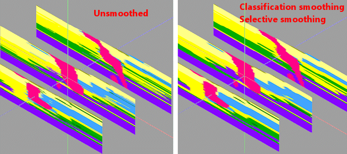
In the example below, an unsmoothed lithology model is shown in 3D panels (left side). On the right, the lithology model was smoothed very slightly, using the classification method, to get rid of some of the small material crenulations. In addition, a Selective filter was applied for the pink intrusive material so that it would not be smoothed at all.
- Create 3-Dimensional Diagram: Insert a check here if you want to create a plottable 3D diagram of the resulting solid model. Expand this item to establish the diagram settings.
- Diagram Type: Choose Isosurface to display the solid model as if enclosed in a "skin". Choose All Voxels to display color-coded voxels. (More.)
- Iso-Mesh: Use this option to plot a series of polylines that represent three-dimensional contours at a user-defined cutoff. Expand the heading to establish the settings. (More.)
- Color Scheme: Click on the Options button to the right to access a variety of pre-set color schemes, or to create your own. (More.)
- Reference Cage: Insert a check here to include vertical elevation axes and X and Y coordinate axes in the 3D diagram. Expand this item to set up the cage items. (More.)
- Include Legend: Insert a check here to include an index to the colors and G values in the diagram. (More.)
Step-by-Step Summary
- Double-check that you have a real number RockWorks solid model which will be the input file for this program.
- Access the RockWorks | Utilities program tab. It is not necessary to enter data into the main datasheet because RockWorks will be manipulating an existing solid model.
- Select the Solid | Filters | Smoothing Filter menu option.
- Enter the requested menu settings, described above.
- Click the Process button to continue.
The program will load the input file, compute the new value for each solid model node using the requested filter size. This process will be repeated for each node in the entire source model. If Iterations was set to >1, the entire model will be passed though the "smoother" for the requested number of times. The resulting node values will be stored in a new solid model on disk under the output file name you selected. If you have requested a diagram, it will be displayed in a RockPlot3D tab.
- You can adjust any of the input options along the left side of the window and click the Process button again to regenerate the model and display.
! Each time you click the Process button, the existing 3D display will be replaced.
- View / save / manipulate / print the image in the RockPlot3D window.
 Back to Solid Menu Summary

RockWare home page