( The Section, Profile, Projected Section, and Fence Options Menu )
Use the Options menu tools in the RockWorks cross-section, profile, projected section, and fence-picking window to adjust how the boreholes are displayed in the window.
Menu Options
- Replotting
- Automatic: If selected, the borehole locations and log traces will be redrawn each time the section trace is updated. This keeps the window current but can slow the program if many wells with detailed log traces need to be refreshed. Turning this item off eliminates the refreshing of the screen.
- Manual: This option will replot the section map display only if the Redraw button is clicked.
- Show Borehole Locations
- Label Boreholes: If checked, each borehole location will be labeled with its name. Deactivate this setting if the view is cluttered.
- Log Traces: If activated, log traces will be displayed. It's helpful to leave this on if you are creating a projected log section, and the borings are deviated and section clipping is activated, as a visual cue to ensure portions of logs are included (or excluded) from the cross section.
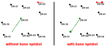
- Show Base Symbol: Check this to include a square symbol at the end of the borehole trace line, indicating the borehole base.
- Display Raster Base Map: Check this option if you want to display a raster map behind the boreholes in the Selection Map window.
- Raster File: Click to the right to browse for the file which contains the map image. BMP, JPG, EMF/WMF, PCX, PNG, TGA and TIF image formats are supported.
- Geo-Reference: Expand this heading to define the map placement relative to your borehole coordinates.
- Output Dimensions: Choose this option if the current output dimensions represent the border coordinates for the image you've selected.
- Manual Dimensions: Click in this radio button if you want to type in the X and Y coordinates for each bitmap corner. Expand this heading to enter those coordinates.
! RockWorks assumes that these coordinates match the coordinate system and units defined in the Output Dimensions.
- Minimum Easting: Enter the X (Easting) coordinate represented along the western edge of the image (X-Min).
- Minimum Northing: Enter the Y (Northing) coordinate represented along the southern edge of the image (Y-Min).
- Maximum Easting: Enter the X (Easting) coordinate represented along the eastern edge of the image (X-Max).
- Maximum Northing: Enter the Y (Northing) coordinate represented along the northern edge of the image (Y-Max).
- World File: Choose this option if there is an accompanying World File which defines the image extents. Expand this heading to select the world file.
- World File : Click on the small open-file button to the right
 to browse for the World file to be used for georeferencing the selected image.
 Watch Video: http://youtu.be/Det9JgpBao0
- Warn User if Endpoint(s) Are Outside Project Area: If checked, the program will warn you that any section, profile, projected section, or fence panels that extend past the current project dimensions have been truncated to the project boundaries. If left un-checked, the truncation will occur without offering you this warning.
- Automated Fence Panel Spacing Method: (displayed for Fence Selection Maps only)
-
- Fixed Number of Panels: Click in this radio button to create a specified NUMBER of fence panels in the available area. This is the easiest pre-set panel spacing option.
- Panels: Enter the number of panels to be drawn. If you enter "5", for example, the program will create 5 fence panels across the study area for the vertical, horizontal, and/or diagonal layout you choose.
- Distance-Based: Click in this radio button to create panels at a specified DISTANCE increment across the study area.
- Distance: Type in the desired distance between fence panels. This must be entered in your study area's map (X,Y) units. For example, if you enter "100", then the program will create fence panels at 100-unit (feet, meter, etc.) increments across the study area for the vertical, horizontal, and/or diagonal layout you choose.
- Tip: If you aren’t sure what distance to enter, you can click Cancel to close the Spacing Options window, and refer to the X and Y coordinate listing at the bottom of the Fence Selection Map window to determine your map units. As you move the mouse pointer around the borehole locations, note that the coordinates are updated.

RockWare home page