The Borehole Manager Orientation tables are used to enter downhole survey measurements (depth, bearing, and inclination) for non-vertical wells. If a well is vertical, its Orientation table should be left blank.
Accessing the Orientation Table
- Access the Borehole Manager
- Create a new project as necessary.
- Create a new well if necessary, or click on the existing well to be edited.
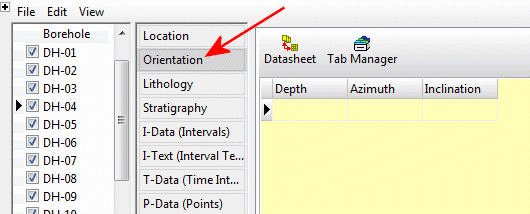
- Click on the Orientation table for the well.
Orientation Fields
- Depth: Enter the first depth at which a downhole survey measurement was made.
! The depth units must be the same as the Vertical units you defined for the project (and which are displayed on the Location table). For example, if the elevation and TD for the hole are shown there in feet, then the depth listings here must be in feet as well.
! The depth values must be positive.
- Azimuth: Enter the bearing of the well at this depth. The bearings must be expressed in decimal azimuth degrees (0 to 360, with 0 = north).
- Inclination: Enter the inclination at this depth.
- The default format in RockWorks is a convention in which zero is a horizontal line, -90 points straight down, and +90 points straight up.
- You can click on the Orientation Axis button at the top of the table to specify which survey format your data adheres to:
-
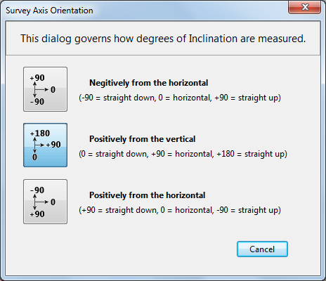
Note that the format you select will apply to all of the boreholes in the project.
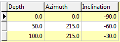
- Repeat this process for additional downhole survey locations. If you have an inclined drill hole, only one survey listing is needed. Below is an example of how a detailed survey might be entered.
Other Notes:
- You can use the Tab key to advance from cell to cell in the table.
- There is no limit to the number of survey points that you may list for each drill hole.
- Survey data must be listed in a sequential order, from the start of the hole to the end.
- The "start" of the hole may be lower in elevation than the "end" of the hole if the boring curves back on itself.
- RockWorks uses an averaging method of drawing the drill hole trace based on the survey data in order to create smooth bends. Compare the following cartoons, based on the data shown. The hole on the left abruptly turns at a depth of 100 to follow the new survey inclination (not realistic) while the hole on the right curves to the horizontal dip at 100 feet.

See also: Computing Downhole Survey Coordinates
 Back to Data Introduction

RockWare home page