In this lesson, you will get a quick view of one I-Data component (Benzene) as entered for the project’s boreholes, by generating 3D benzene logs for the currently-enabled boreholes.
- Enable all boreholes: Back at the Borehole Manager, select Edit | Enable All Boreholes. (Or click the
 button on the toolbar to the left of the borehole names.)
- To create the 3D logs, click on the Striplogs menu, and then click on 3D Striplogs.
This window has several sections:
The left side offers the Main Options, where general diagram settings are established.
The 3D Log Design tab at the top of the window is where you establish the log-specific settings.
- Establish the general diagram settings in the Main Options pane.
 XYZ Clipping: Uncheck this.
- Draped Image: Unchecked.
- Floating Image: Unchecked.
 Perimeter Cage: Check this.
- Legends: Uncheck this.
- Infrastructure: Unchecked.
- Other 3D Files: Unchecked.
- Output Options
- Display: Check this so that the diagram is displayed on completion.
- Save: Unchecked.
- Export: Unchecked.
- Establish the log settings by clicking on the 3D Log Design tab.
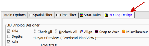
- The left pane is where you choose what type of data is to be displayed in the logs (the visible items).
- The upper-right pane is where you see a plan-view Preview of the active log items. You can drag the items to adjust their relative placement.
- The lower-right pane displays specific Options for the log item that you click on.
Choose the items you want to see in the logs by inserting a check-mark in the following items in the list along the left:
- Title: The drill hole name will plot above the logs.
- Axis: The logs' axes will be shown with a solid line.
- I-Data #1: The logs will contain a column illustrating interval-data values. You can include up to 4 different I-Data tracks; we'll display only one in this lesson.
When you insert a check in the I-Data #1 item, you'll see a purple circle displayed in the plan-view Preview pane.

- Track: At the top of the Options pane, click on the Track heading and choose Benzene Soil as the data to be represented in the logs.
- G Value Filter: Be sure this is left un-checked. In your own work this can be used to display only high or low values in your logs.
- Resample: Be sure this is also left un-checked. In your own work, these settings can be used to thin the number of downhole measurements displayed (for densely sampled drillholes) or to include zero-value "bogus" points to add control to sparsely-sampled holes.
- Column Attributes:
- Column Title: This should be blank. If text is displayed for this prompt, delete the text.
- Column Radius: You can adjust the size of the column by dragging on one of the corner handles. Note the Column Radius setting in the lower-right Options pane. As you resize the circle, the Radius setting will be updated. Drag the I-Data #1 circle until the Column Radius is about 2.0.
! You can simply type 2.0 into the Column Radius prompt, if you prefer.
- Column Offset
- Offset Direction: This should reflect the current offset, in azimuth degrees, from the axis of the log. It can be left at zero.
- Offset Distance: Adjust the placement of the column relative to the axis of the log by dragging the circle in the Preview pane. Be sure the I-Data circle is on the center of the log axis.
! You can simply type 0.0 into the Offset Distance prompt, if you prefer.
- Scaling: Click this tab and select Automatic.
- Appearance:
- Plot Interval Labels: Leave this unchecked (it's used to plot value labels down the log).
- Color: Choose Cold -> Hot Colors. This will color-code the logs based on Benzene Soil values.
- Shape: Choose Oblates.
! You can drag the splitter between the Preview and the Options panes to create space, if necessary.
- None of the other log items should be checked.
- Faulting: Click this tab to set up your Faulting Options in your striplog display and to modify fault options. (Read this for more details.)
- Click the Continue button at the bottom of the Multiple 3D Striplogs window to proceed.
RockWorks will create a log for each enabled borehole, including well name at the top, and color-coded Benzene Soil disks displayed down the log. They will be displayed in a new RockPlot3D tab.
The image is displayed in the pane to the right, and the image components as well as the standard reference items are listed in the pane to the left. The expandable/collapsible list on the left is called the data tree.
- Adjust the Reference items: Turn off the World Outline (if it’s on), by clearing its check-box in the upper portion of the left-hand listing. (Since there’s a reference grid in this image, the world outline is redundant.) Be sure the Axes and Labels are both turned on.
- Set the view to a fixed viewpoint: Click on the View menu and choose Compass Points | East.
- Since the logs will appear lined up behind each other, click and hold on the south-north midline and drag slightly to the right to rotate around the vertical axis so that you can see the background logs. Try to keep the image straight up and down. Release the mouse button. Next, click and hold on the top-base axis line and drag slightly downward to rotate the image around the horizontal axis. This will give the display a 3-dimensional view.
! If you lose track of where you are in the 3D display, you can always return to the View menu to choose a pre-set viewpoint, such as Compass Points | East, or Above | Southwest (the default view).
- Zoom into the logs along the left side of the display: Click the Zoom button
 in the toolbar, and click and drag in the image as shown below to draw an enlargement rectangle.

Note that you can also enlarge / reduce 3D views using the Percent drop-down at the top of the window.

- Re-adjust the rotation if you wish, even when zoomed in. Use the Pan tool
 to move the current view back and forth, up and down. To zoom back out, just click once on the Zoom Out button
  .
.
- Turn on/off logs: Expand the Logs group item in the data tree to the left, to see the individual boring names. You can turn entire logs on and off simply by checking/clearing their respective check-boxes. Try this for a few borings.
- Turn on/off log items: In addition, if you expand an individual borehole in the data list, you’ll see its title and Oblates group. These, also, can be turned on and off for each well.
- Save this 3D log data: Select the File | Save As command. In the displayed window, type in this name: I-Data Logs and click Save. RockPlot3D will save this information on disk under that name, with an .Rw3D file name extension. In later lessons, you can append these logs to other 3D diagrams.
- Close the RockPlot3D window by clicking in the Close button (X).
