An "IDW Solid Modeling Sector Table" is used to define one or more 3D regions within which the Inverse-Distance Table-Based solid modeling method will look for points as it's assigning a node value, and apply the user-defined modeling settings.
! You can store multiple 3D IDW sector tables in your project database. If you assign detailed names they'll be easy to distinguish when you're selecting which to use. 3D IDW sector tables can be accessed in the Project Manger tab of the main RockWorks program window, under the Project Tables | Map/Model Tables grouping.
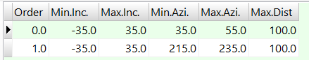
- Order: The values are assigned automatically as you edit the table. You can edit the Order values to re-order the rows.
- Min.Inc., Max.Inc.: These columns define the minimum and maximum angle from horizontal (negative = below horizontal, positive = above horizontal) to be searched for points.
- Min.Azi., Max.Azi.: These columns define the minimum and maximum azimuth bearing (0 to 360) to be searched for points.
- Max.Dist: This defines the maximum distance from the model node, within the indicated directional and angle sector, to be searched for points.
In the above example, for each solid model node being interpolated, the program will search out to 100 feet along a 35 to 55 degree bearing and 215 to 235 degree bearing, within 35 degrees above and below horizontal. Any control points located within these sectors, will be used for node interpolation as defined in the algorithm's options.
- You may list as many 3D sectors as you wish.

RockWare home page