- With the LogPlot program running, click on the Log Design tab to bring it to the front.
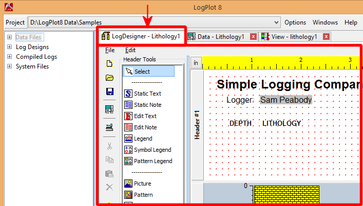
LogPlot will display the Log Design window. This window always displays the last design you were working with, or (if new) the first sample log in the library.
- If the Log Design window already displays the "Lithology1" file (also shown on the Design’s stick-up tab shown in the illustration above), you can skip down to #4. If not, continue with 3.
- If necessary, open the "Samples" Directory that was installed by LogPlot (the default location is "..\Documents\LogPlot Data\Samples"). Click on the Project button at the top left of the LogPlot window.
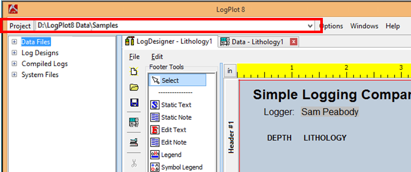
and browse to the LogPlot Data\Samples folder. Click Open to open that folder into the Project Manager.
You should see a listing of a few data and design files.
! Note - in your own work, most of the sample files are installed in sub-folders inside the Samples folder ("Environmental-Geotechnical Samples", "Govt Agency Samples", etc.). See the listing of all of these sample files to pick a design as a starting point for your own.
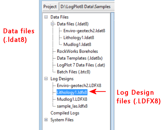
- Locate the LogDesign file named "Lithology1.ldfx8" and double-click on it.
The sample design will be displayed in the Log Design window.
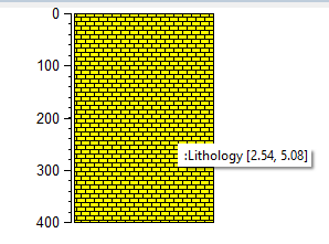
This log contains a simple header (displayed in the upper pane); a log body with only a depth bar, a lithology pattern column (displayed in the middle pane); and a footer (bottom pane) that includes an automatic page number entry.
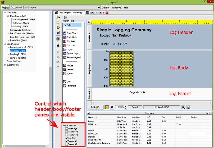
- You can use the Visible Sections checkboxes to define which header/footer/body panes are visible within the Design window. You can change the viewing size of the visible panes by clicking on the pane divider, holding the mouse button down, and dragging it up or down.
- Try accessing the settings for the Lithology Pattern column by double-clicking on its picture in the log body section of the design screen. The program will display the Lithology Column Setup window which declares the "name" of the pattern column, its horizontal location in the log, and whether or not the column is to be outlined with a solid line frame.
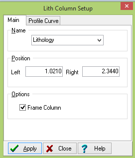
The "name" is important. LogPlot will match data to this column based on this name.
- Click the Close button to close this window.
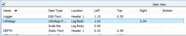
- Back at the design screen, position the screen pointer on top of the pattern column. You'll see the column's name, "Lithology", displayed in the pop-up "hint" window. The information also is displayed in the item view pane where the selected item is highlighted.
- Now, try moving the pattern column by clicking on its picture, holding down the mouse button, dragging it to the right, and releasing the mouse button. You can also move the item using the arrow keys. Holding the Ctrl + arrow keys will move the item in one grid space increment.
- Select the Edit | Undo menu option to move the column back to its original location. Ctrl + z will also perform the undo function.
Finally, you should always check the design's page size. The page size will be determined by the printer you have established in Windows, and the paper size and orientation you have established there. The page size and paper orientation is stored in the log design file.
 Click on the Page Setup button along the left side of the Log Design window. (Or select that command from the Design window's File menu.)
Your default Windows printer name should be displayed in the upper-right section of the window. It will also show the printable portion of the current paper selected for that printer (such as 8.1668" x 10.6667" for US Letter-size paper). The Change Printer Settings button can be used to access the Windows Printer Setup options, to change the default printer for LogPlot, to modify the paper size, etc.
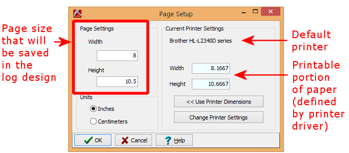
The left side of the window defines the page size for the log design. NOTE that the settings in your print setup window will probably be different than those shown.
- Select the desired output units (inches or centimeters) by clicking in the appropriate radio button to the right. (This will also determine the units in the ruler in the design window.)
- Click the << Use Printer Dimensions button. This will set the log dimensions to the printable dimensions of your paper, in the selected units.
- Click OK at the bottom of the window to return to the design screen.
 Save the design changes by clicking on the save-file button or choose the File | Save menu option.