
Use the Striplog Bitmaps check-box to plot downhole raster images in vertical 3D logs. These images can represent raster elogs, digital core photographs, etc. The image depths and names are read from the Bitmaps table in the RockWorks Borehole Manager database. When you click on the Bitmaps item in the layout window you’ll see the following settings in the pane to the right.
Bitmap Column Options
- Type of Bitmap To Display:
- All Types: Choose this option if all of the raster images currently listed for the boreholes are to be plotted in the Bitmap column. If you have defined multiple Bitmap Types, and want to plot all of them, just be sure that they exist at different depth ranges.
- Specific: Choose this option if you want to plot a selected Bitmap Type only.
- Bitmap Type: Click to the right to choose the bitmap category to be displayed at this time. This list is pulled from the Bitmap Types table. You can choose the name from the drop-down list, or you can click the small button to view the Bitmap Types table and select the category there.
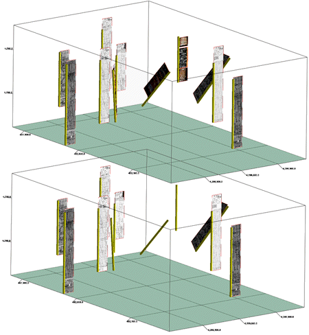
In the example shown here, the upper scene was generated with All Types selected, and the logs display scanned elogs, core photos, outcrop photos - all images in the database for those boreholes. By contrast, the lower scene was generated with the Raster Logs only.
-
- Aspect Ratio: Use these settings to determine if the original bitmap aspect (width:height ratio) will be preserved or if it will be horizontally stretched or reduced to fill the designated column.
- Preserve: Choose this option to maintain the original image aspect ratio so that the image is not distorted. This is especially useful when viewing poor-quality raster logs. The downside is that the image has no regard for the designated column width. It can be narrower or wider depending upon the width:height ratio of the original image.
The following example depicts two versions of a measured section across the face of a small hill plotted as a deviated borehole.
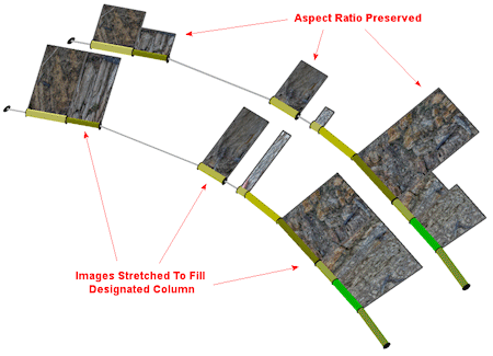
- Stretch/Reduce: Choose this option if you want the image to be stretched or reduced to fit the designated log column width, regardless of the original image aspect ratio. This produces a more uniform appearance within cross-sections but the images may be distorted.
- Offset Direction: This reflects the position of the column, relative to the log axis (center), with 0 = north, 180 = south, and so on. As you click and drag the Bitmaps column in the Layout Preview pane (top), this value will be updated. Conversely, if you edit the azimuth direction in this prompt, the Preview will be updated.
- Offset Distance: This represents the distance of the center of the Bitmap column from the log axis (center), expressed as a percent of the output dimensions. As you reposition the column in the Layout Preview pane at the top of the screen, this value will be updated. And, if you edit the offset distance here, the Preview will be updated.
- Column Radius: This represents the width of the Bitmap column, established as a percent of the output dimensions. As you click and drag to resize a column in the Layout Preview at the top of the window, this setting will be updated. If you edit the radius via this prompt, the size of the column in the Preview will be updated.
- Border: Insert a check here to include a border around the bitmap image(s), as 3D tubes that will be drawn around the perimeter of the image.
- Tube Color: Click here to choose a color for the border tubes.
- Tube Radius: This setting establishes the radius for the tubes, as a percent of the project size. Default = 0.02
See also Miscellaneous Options for for settings that establish the font size and offset for the column title.
 Back to 3D Striplog Options

RockWare home page