RockWorks | Utilities | Imagery |
Digitize (Extract Coordinates from Image)
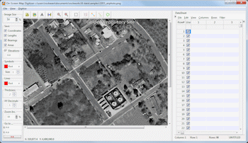
This program is used to import a bitmap image (BMP, JPEG, TIFF, WMF, EMF, PNG, GIF, TGA, and PCX format), calibrate it to global coordinates, and digitize points, lines, polylines, and polygons. As the items are selected, the global coordinates are stored within an editable data window along the right side of the screen. This data may then be copied into other applications.
Possible applications include:
- Digitizing xy coordinates for various features (e.g. well-locations, sample sites, etc.) for subsequent mapping within other programs (e.g. RockWorks point-mapping utilities).
- Digitizing linear features (e.g. fractures) for processing by RockWorks lineation analysis software (lineation gridding, rose diagrams).
- Digitizing polygons for lease boundaries.
- Digitizing points along a contour map (changing the elevation accordingly) and then gridding the data within RockWorks.
Menu Options
Step-by-Step Summary
Menu Options
Image Window
- File menu
- Load Bitmap: Open the raster image to be digitized.
- Calibrate: Calibrate image relative to global coordinates.
- Exit: Terminate program and return to main RockWorks menu.
- Edit menu
- Copy bitmap to clipboard: Copies the currently-loaded bitmap into the computer's clipboard.
- Bitmap Coordinates: Computes the global corner-point coordinates for the bitmap (assuming that the bitmap has been calibrated)
- View menu
- Options: Establishes various bitmap-digitizer options.
- Go To: Sets the user-entered X,Y coordinate at the center of the window's display (an orientation tool). Enter the global coordinates for a known point. The program will then automatically reposition the map on the screen such that the selected coordinates correspond to the center of the diagram.
- Size menu: This is a drop-down menu below the File/Edit/View menu bar. It is used adjust the view size of the raster image. Click the up- or down-arrow to increase or reduce the display size of the image. See also the Zoom In/Out tools under the Mode menu, below.
- Mode menu: This is a drop-down menu below the File/Edit/View menu bar. It is used to do the actual work of this program. The line colors (etc.) used to represent the digitized items AND the flags (such as "LINE") used to represent them in the data window are all adjustable using the Options command, listed above.
- Navigation tools: Use the Center Image, Zoom In and Zoom Out tools to adjust the display of the bitmap image in the program window.
- Lines: These tools allow you to point-and-click the beginning and ending points of single line segments. Their specific measurements (point coordinates, bearings, or lengths) will be posted in the data window.
- Digitize Lines: It will post the X1Y1Z1X2Y2Z2 coordinates after a "LINE:" flag in the data window. The Z values will be read from the Elevation box at the top of the window.
- Measure Line Bearings: It will post the azimuth bearing from endpoint 1 to endpoint 2 after a "BEARING:" flag.
- Measure Line Lengths: It will post the lengths of the individual lines after a "DISTANCE:" flag in the data window.
- Points: This tool records the X and Y coordinate for each point you click. It will also post the value listed under Elevation as the Z value for each point.
- Polygons: These tools allow you to point-and-click the points along the perimeter of a polygonal area. Their specific measurements (vertex coordinates, area, or perimeter) will be posted in the data window
- Digitize Polygons: The program will record a "POLYGON:" flag in the data window and will post the XYZ coordinates for each vertex you digitize around the perimeter of the polygon. To close the polygon (with an "END-POLYGON:" flag) just double-click on the last point prior to return to the beginning point.
- Measure Polygon Area: The program will record the area of the polygon you digitize, after an "AREA:" flag in the data window. It does not post the polygon vertex coordinates.
- Measure Polygon Boundary: The program will record the total length of the polygon's perimeter lines after a "PERIMETER:" flag in the data window. It does not post the polygon vertex coordinates.
- Polylines: These tools allow you to point-and-click the points at each vertex of a multi-segmented line, such as a log curve or open contour line. Their specific measurements (vertex coordinates and total length) will be posted in the data window.
- Digitize Polylines: The program will record a "POLYLINE:" flag in the data window and will record the XYZ coordinates for each vertex you digitize along the polyline. To terminate the polyline, double-click on the last point.
- Measure Polyline Length: The program will record
Data Window
- File menu
- New: Creates a new data file for recording digitized items.
- Open: Opens an existing data listing that has been saved in this data window.
- Save: Saves the contents of the data window within an ASCII text file.
- Save As: Saves the contents of the data window within an ASCII text file under a different file name.
- Export:
- RockWorks Utilities Datasheet: Transfers the data listing to the Utilities datasheet.
- Edit menu
- Cut: Removes any selected data fields and places the contents in your computer's clipboard memory.
- Copy: Copies any selected information in the data window to the computer's clipboard.
- Paste: Pastes into the data window any information currently in the computer's clipboard.
- Delete: Deletes the contents of any currently-selected data cells.
- Select All: Selects all information in the data window.
- Remove Rows: Deletes one or more adjacent rows from the data window..
Step-by-Step Summary
- Access the RockWorks Utilities program tab. This program does not read data from any datasheet, so you don't need to open an .RwDat file at this time. It does read an existing raster (GIF, PNG, JPG, PCC, PCX, AFI, VST, TGA, TIFF, BMP) image; be sure you have that handy and that it resides in the current project folder.
- Select the Imagery | Digitize menu option.
- Use the File | Load Bitmap command to open the image from which you wish to capture X,Y coordinates.
- Use the File | Calibrate command to establish the known points on the diagram, from which subsequent points can be digitized. (More.)
- Use the File | Options command to establish various digitizing parameters. (More.)
- Once you are ready to digitize lines, points, polygons, or polylines, choose the desired operation from the Mode menu and digitize away, as discussed above.
- Use the Data Window's Edit menu tools to copy the data window's listings to the clipboard, or use the File | Save option to save the entire contents of the data window to an ASCII file, or the File | Export option to transfer the measurements to the Utilities datasheet.
 Back to Imagery Menu Summary

RockWare home page