The Borehole Manager’s Fractures table is used to enter the depth, bearing, and dip of downhole fractures. These can be displayed as oriented disks on individual logs and log sections. They can also be interpolated into a solid model representing fracture proximity which can be represented visually as a profile, section, fence diagram, plan map, or isosurface/voxel display.
Accessing the Fractures Table
- Access the Borehole Manager
- Create a new project as necessary.
- Create a new well if necessary, or click on the existing well to be edited.
- Click on the Fractures table for the well.
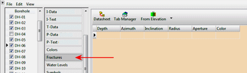
Fracture Data Fields
These instructions are for hand-entering the data; please see the links at the end of this topic for other options.
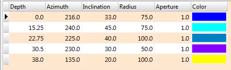
- Depth: Type in the measured depth for the first fracture you wish to record.
! The depth units must be the same as the Vertical units you defined for the project (and which are displayed on the Location table). For example, if the elevation and TD for the hole are shown there in feet, then the depth listings here must be in feet as well.
! The depth values must be positive.
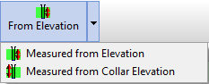
- From Elevation / From Collar Elevation: Use this button at the top of the table to define for this borehole which datum your depths were measured from.
- Choose Measured from Elevation if the depths were measured from the ground elevation (entered as the "Z (Elevation)" field in the Collar Coordinates tab). This is the default setting.
- Choose Measured from Collar Elevation if the depths were measured from the collar elevation (entered as the "Collar Elevation" field in the Collar Coordinates tab).
- Azimuth: Enter the dip bearing in azimuth degrees (from 0 to 360) of the fracture.
! For non-vertical holes, it is assumed that the Azimuth and Inclination measurements have been corrected for borehole orientation.
- Inclination: Enter the angle in degrees from horizontal (0 = horizontal, 90 = straight down).
- Radius: Enter the fracture radius, in your data units (feet, meters). This will determine the size of the fracture disk as displayed on 3D striplogs, and will affect any fracture modeling you perform.
! This setting will be ignored if, during strip log setup, you set the Fractures / Dimensions to Fixed and enter a value there.
- Aperture: Enter the fracture thickness. When displayed in RockPlot3D this will affect the thickness of the fracture disk as it’s displayed with the logs. The fracture aperture is entered as actual thickness units, in the same units as your other downhole data. For example, if your other log data is entered in feet, the fracture aperture must also be entered as decimal feet.
! This setting will be ignored if, during strip log setup, you set the Fractures / Dimensions to Fixed and enter a value there.
- Color: Double-click in this cell and choose a color for the fracture "disk" that will be displayed in the logs and log sections.
- Repeat this process for additional downhole fractures. Example:
See also
- Edit Data as Datasheet for displaying the table as a row-and-column datasheet, for copy/pasting, resampling, etc.
- Importing Borehole Data for information about pulling in data from other sources (ASCII, Excel, etc.).
- The Striplogs menu for tools to display the fractures in logs and log profiles/sections (observed data).
- The Fractures menu for tools that interpolate fracture locations as a solid model, for display as profile, section, and fence panels, as plan maps, and as a 3D isosurface or voxel block (interpolated data).
 Back to Data Introduction

RockWare home page