Use this program to:
See also
Modeled Stratigraphy Sections for grid-based cross sections with multiple slices
Striplog Sections for multi-slice sections with linear correlation options
Feature Level: RockWorks Standard and higher
Menu Options
Step-by-Step Summary
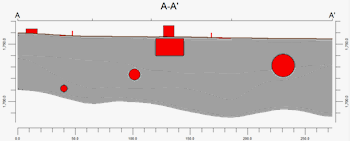
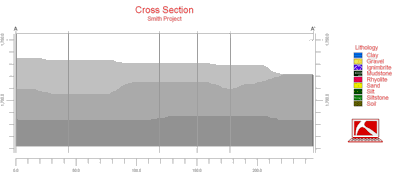
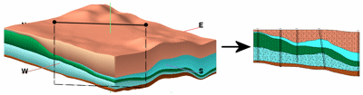
Follow these steps to create a 2-dimensional (flat) vertical profile of the project's interpolated stratigraphy:
If Interpolate Surfaces is turned on, the program will create grid models of the surfaces and bases of the formations listed in the Stratigraphy tabs, storing the models in the current project folder. The grid file names are assigned automatically, based on the formation: "formation_top.RwGrd" and "formation_base.RwGrd". Two grid models will be created for each formation using the specified gridding settings.
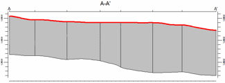
It will then look at the coordinates specified for the profile cut and determine the closest nodes along the cut in each grid model. It will construct a vertical profile to illustrate the stratigraphic elevation, using the colors and/or patterns defined for the strata in the Stratigraphy Types Table. If requested, it will fill the layers, and add all peripheral, border, and other layers to the output. The completed diagram will be displayed in a RockPlot2D tab in the Options window, if requested.
! * If the stratigraphy surfaces look OK and you just need to adjust one of the diagram settings, you don't need to keep re-gridding over and over: Un-check Interpolate Surfaces and the profile will be built with the new diagram settings from the existing grid models.
![]() Back to Stratigraphy Menu Summary
Back to Stratigraphy Menu Summary
![]()