Click on the Superface tab to access the filter settings.
- Automatic (Based on Borehole Collar Elevations): Easiest. The program will automatically interpolate a surface representing the elevations at the top of the boreholes (using current project dimensions and the inverse-distance gridding method) and use that to determine above-ground nodes.
- Manual (Based on user-defined grid model): Choose this option to specify your own, existing grid model to serve as the solid model constraint. This can be helpful if ground topography is not adequately represented by the Automatic method, if you have a separate digital elevation model to use, etc.
- Grid Model: Click here to browse for the existing grid model (.RwGrd file) to serve as the upper bounding surface.
! The grid model must have the same X,Y dimensions and node spacing as the solid model being constrained.
! If you're working with T-Data: By using aquifer surfaces for the same time interval as constraining grids, it is possible to generate models/diagrams that show both the concentration levels for a contaminant as well as the changes within the aquifer thickness. See the T-Data tutorial lessons for details.
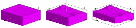
This example shows an unfiltered 3D solid model (left), a model with an upper surface filter applied (middle) and a model with both an upper and lower constraining filter applied.
- Grid Model: Click here to browse for the existing grid model (.RwGrd file) to serve as the upper bounding surface.
-
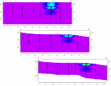
This example shows the same models displayed in cross section.
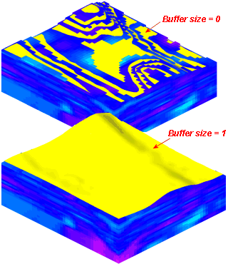
- Buffer Size: Use this setting to define how close to the constraining surface the filtering is to occur. A setting of "0" filters the solid model as closely as possible to the grid surface. Depending on the vertical resolution of the .RwMod file, this can sometimes allow voxels to poke through the filtering surface. A setting of "1" will add a distance equivalent to one vertical node below the filtering surface (you can refer to your project dimensions, and the vertical node spacing), thus creating a buffer between the model and the grid.
Click on the Subface tab to access the filter settings.
- Automatic (Based on maximum borehole depths): Easiest. The program will automatically interpolate a surface representing the borehole bases (using current project dimensions and the inverse-distance gridding method) and use that to determine nodes that lie below where drilling stopped.
- Manual (Based on user-defined grid model): Choose this option if you wish to specify your own grid model to serve as the solid model constraint.
- Grid Model: Click here to browse for the existing grid model (.RwGrd file) to serve as the lower bounding surface.
- Buffer Size: Use this setting to define how close to the constraining surface the filtering is to occur. A setting of "0" filters the solid model as closely as possible to the grid surface. Depending on the vertical resolution of the .RwMod file, this can sometimes allow voxels to poke through the filtering surface. A setting of "1" will add a distance equivalent to one vertical node below the filtering surface (you can refer to your project dimensions, and the vertical node spacing), thus creating a buffer between the model and the grid.