Surface profile lines can be included in Borehole Manager profiles, cross sections, and fence diagrams to show the location of a surface, typically representing the ground surface. Surface profiles can also be created in the ModOps | Grid menu. When included in 2D diagrams, the surface profile will be drawn as a line. When included in 3D diagrams, the surface profile will be drawn as a 3D tube.
In the Borehole Manager programs, you can activate the display of the surface profile line by inserting a check-mark in the Surface Profile option. Click the item's tab to access the following settings.
 Surface Profile
- Input
-
- Grid Model: Click on the small button to the right to browse for the name of the existing grid model (.RwGrd file) that is to be profiled. This grid model must already exist in your project folder. Some examples: If you have created a surface contour map of the borehole locations (Borehole Operations | Map | Borehole Locations) you could use that surface grid model as the source of the profile line in a lithology, stratigraphy, P-Data, I-Data, or other fence diagram. Or, if you have imported digital elevation data in the form of a grid model, you could use that as the source for the profile line.
- Fence Diagrams only
- Profile:
- Color: Color to be used when plotting the lines (2D) or tubes (3D) that depict the surface profile.
- Radius: Radius (in percentage units) to be used when plotting profiles.
- Smoothing: If set to zero, the profile will have a "stair-step" appearance that is caused by the discrete nature of the grid model.
- Vertical Lines at Endpoints: If desired, vertical lines can be plotted along the edges of the profile. The elevation at the base of these lines is defined by the Base Elevation (see below).
- Color: Color to be used when plotting vertical edge lines.
- Radius: Radius (in percentage units) to be used when plotting vertical edge lines.
- Horizontal Line along Base: If desired, a horizontal line can be plotted along the base of each profile. The elevation for this line is defined by the Base Elevation (see below).
- Color: Color to be used when plotting horizontal base line.
- Radius: Radius (in percentage units) to be used when plotting horizontal base line.
- Base Elevation: The elevation that is used for plotting the vertical edges and the base can be defined in one of two ways:
- Based On Project Dimensions: The base elevation will be defined by the minimum z coordinate that is specified within the project dimensions menu.
- Manually Specified: The base elevation will be defined by the following setting.
- Elevation: Elevation at which base line will be plotted.
- Profiles and Cross-Sections
- Polyline Attributes:
- Line Style & Color: Click on the sample to choose a line style, thickness, and color for the profile line.
- Smoothing: Click on this item to set the number of smoothing passes. If set to zero, the profile will have a "stair-step" appearance that is caused by the discrete nature of the grid model.
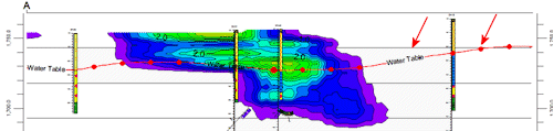
- Add Labels: Check this box to include labels along the surface profile polyline. See the graphic example below, in which the line is labeled "Water Table".
- Label: Type the label text into this prompt.
- Color: Choose the text color by clicking on this box and selecting a color.
- Font Size: Type in the size for the label text characters, as a percent of the size of the project.
- Spacing: Use this prompt to enter the spacing for the text, as a percent of the project size.
- Opaque Background: Check this box if the text is to have an opaque background, and choose the fill color.
- Add Symbols: Check this box to include symbols along the surface profile polyline, as shown in this example (red symbols).
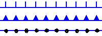 Hatchures: Select this item if the symbols are to be hatchure lines, and choose the position: left side of the line, centered on the line, or on the right side of the line.
- Triangles: Select his item if the symbols are to be triangle shapes, and choose the position: left side of the line, right side of the line, pointing forward along the line, or pointing backward along the line.
- Other: Select this item to choose the symbol design and color by clicking on the Symbol preview.
- Symbol Size: Type into this prompt the size for the symbol, as a percent of the project size. (Default = 1.0)
- Symbol Spacing: Type into this prompt the spacing for the symbols, as a percent of the project size. (Default = 5.0)

RockWare home page